ONLINE HELP
Contents
On-line Help for Loco Operator 3 Version 3.4
Getting Started
This online help is intended as a Loco Operator reference and is quite complicated in places. In order to get your model railroad Wi-Fi network up and running with the minimum effort, it is recommended that the Quick Start document be followed. This takes you through the steps of:
- 1. Getting your locomotive working in Direct Wi-Fi mode.
- 2. Driving your Wi-Fi Loco or Wi-Fi/DCC locomotive.
- 3. Setting up your infrastructure model railroad network and switching your locomotive(s) over to behave as stations on your infrastructure Wi-Fi network.
You can read the Quick Start document at
http://www.wifitrax.com/appNotes/quickStart/Loco-Operator-Quick-Start.pdf
You can also read about networking with WifiTrax in the document Managing your Model Railroad Network
http://www.wifitrax.com/appNotes/Managing-your-Model-Railroad-Wi-Fi-Network.pdf
Install Wizard
There are several tasks that are required to begin using Loco Operator and to manage locomotives and layout devices as you add or remove them from your layout. These tasks can all be accomplished using the features described in the rest of this document, but they can be accomplished quickly using the Install Wizard. Using the Install Wizard avoids the need for you to understand all the features of Loco Operator and can get you into operation more quickly.
When you first install and run Loco Operator, the Install Wizard will start automatically at Page 1. But you can re-enter it at any time as below.
Entering the Install Wizard

You can enter the Install Wizard at any time by tapping the Wizard button in the top right hand corner of the screen.
Install Wizard Page 1 - Define/Modify a Home Network?
Page one is the Start Page of the Install Wizard. It allows you to decide whether you want to create a Home Net based on your home Wi-Fi router, or work without a Home Net. Working with a Home Net is called Infrastructure Mode. Working without a Home Net is called Direct Mode.
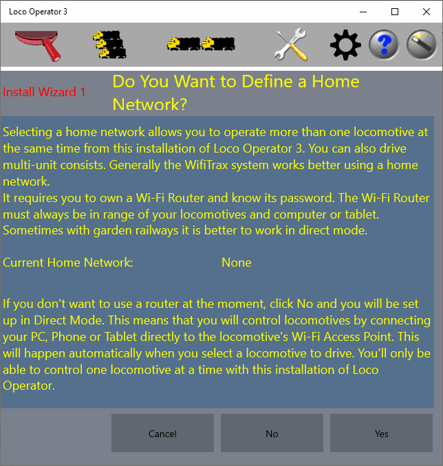
Figure 1 Install Wizard Page 1, when no Home Net exists.
When you enter the wizard when a Home Net has not been created, you have the option to create one. If you have already created it, you have the option to modify it.
If you choose not to create a home net but work in Direct Mode, you can tap the No option. This will take you straight to Page 5 of the Install Wizard where you can immediately scan for locomotives.
Install Wizard Page 2 - Choose Home Network
Page two is the page of the Install Wizard where you can select a visible Wi-Fi Access Point to be your Home Network. Page 2 displays the Wi-Fi access points, visible to your computer that could be your Home Net.
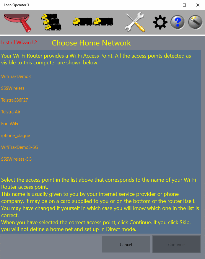
Figure 2 Install Wizard Page 2, here you can select an Access Point to act as your Home Net.
Typically you will see your own Wi-Fi Router as well as some neigboring ones and Telco Hotspots. For your own router, you may see two access points, the second with the label including 5G. The "-5G" ones are 5GHz. WifiTrax controllers (such as those in locomotives) cannot connect to 5G networks. Therefore you must select the 2GHz access point of a router in your own home, which you are able to manage. In the example above, WifiTraxDemo3 and WifiTraxDemo3-5G are access points of our demonstration router. We must select WifiTraxDemo3.
Install Wizard Page 3 - Provide Home Network Details
Page three is the page of the Install Wizard where you define parameters of your Home Net: your Password, Subnet and IP Address range.
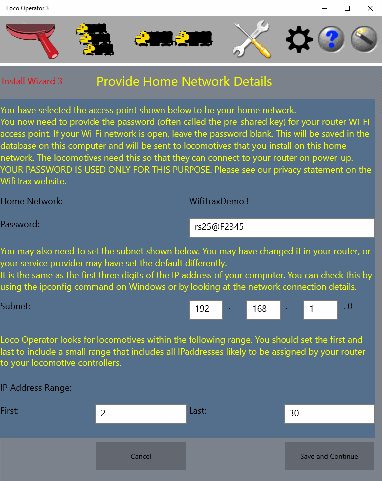
Figure 3 Install Wizard Page 3, here you define your Home Net Password, Subnet and IP Address Range.
At this point you need to find out a bit about your home Wi-Fi network and make some decisions.
Wi-Fi Access points have two important features - their SSID and Password. The SSID (Service Set Identifier) is simply the name of the Wi-Fi access point and the network behind it. The Password (or Shared Key) is the password needed to connect to the access point. Usually home Wi-Fi access points have a password to prevent neigbors or people in the street from connecting and accessing a home network. At this screen, you have already chosen your access point SSID and now need to enter its password so that Loco controllers can be installed. The install process is the means by which Loco Operator configures your WifiTrax controllers so that they will connect to your Home Net each time they power up. It is similar to connecting to Wi-Fi when you are in a hotel or restaurant. You need to select the network name (SSID) and type in the password that they gave you.
A word on privacy: the password is stored in a database on the device you are using. It is only needed for two reasons (1) so that Loco Operator can connect your device to its home net, and (2) so that Loco Operator can send the password to your locomotive or other WifiTrax controller as part of the install process.
So type your own Wi-Fi password into the Password text box. (don't copy the one in the example!!)
In the Subnet text boxes, make sure the Subnet matches the first three digits of your computer's IP address. For instance if your computer's IP Address is 192.168.1.22, use 192.168.1.0 as the subnet. Notice that on the screen, the last digit is forcibly zero. IP Addresses are simply addresses of computers, printers and other devices on a network. Your router usually gives them to each device that connects. If you don't know how to find your computer's IP Address, type something like "Find my IP Address" into Google or your favorite search engine. You will find plenty of help.
Finally, you need to decide on the range of IP Addresses on your Subnet that you will use for model railway controllers in locomotives or layout features. Remember that your router normally assigns IP Addresses, so if you have a lot of computers, phones and things on your network the IP addresses assigned to model trains may be further up the range than you might think. The larger the range, the longer it will take Loco Operator to scan your network looking for locomotives. On the other hand, if you make the range too small, Loco Operator may not see your locos, etc. A good choice is usually from 2 to 20, since 1 is normally occupied by your router.
While we are on this subject, it's worth mentioning that the IP Addresses assigned to locos can change since your Router is in charge of this. If they change you may need to perform a new scan to discover the new IP Addresses. You can avoid this by assigning IP Address Reservations in your router. You can find out about this by typing something like "Reserve IP Addresses" into your favorite search engine.
When you have finished entering these values, make sure any new WifiTrax controllers are powered up on your layout, then tap Save and Continue.
Install Wizard Page 4 - Install Locomotive Controllers
Page four is the page of the Install Wizard where you find new locomotive or other controllers and install them onto your Home Net.
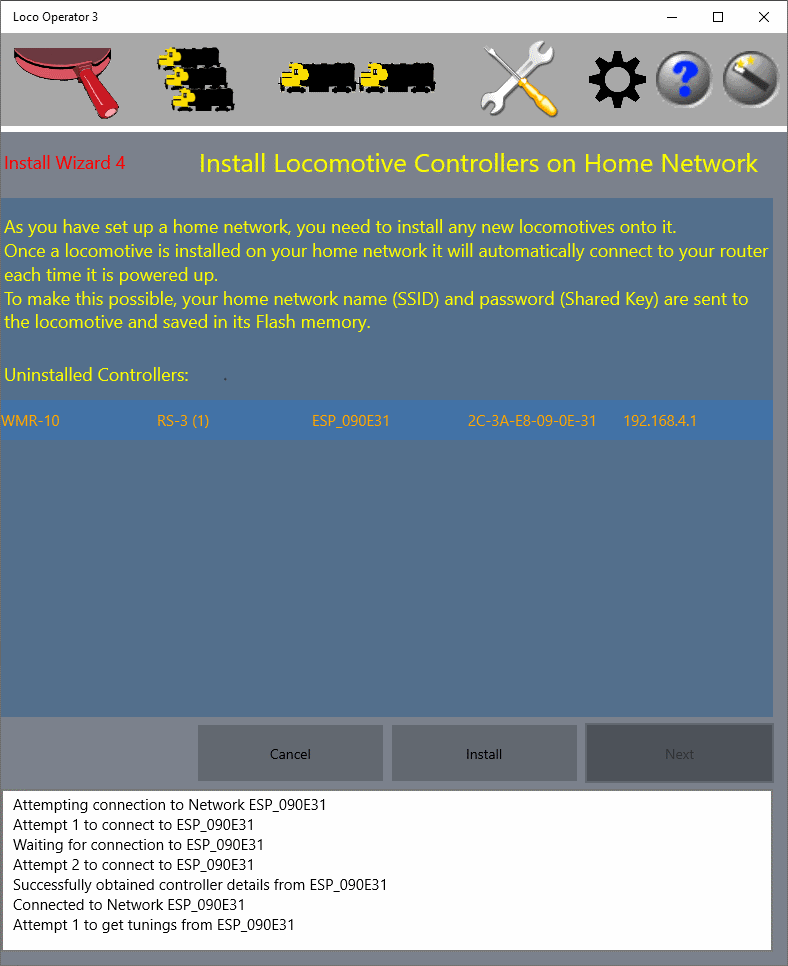
Figure 4 Install Wizard Page 4, here find new locomotive or other controllers and install them onto your Home Net.
When you receive a new Wi-Fi Controller from WifiTrax, whether it is for locomotives, switch machines, power, signals or anything else, it comes with no instructions about which home net to connect to. In the factory, we do not know anything about your home network router, so we cannot set this up for you. Therefore each new controller has to be installed onto your Home Net. This is very simple - it just means sending the SSID and Password to the controller so it can save it and use it to connect to your Home Net each time it powers up.
This screen of the Wizard can do all of this for you since you have already provided your SSID and password in previous screens. In fact, as soon as this screen displays it will look for all WifiTrax controllers that are powered up and find out if they have been installed. Those that have not been installed are listed, as you see in the figure.
So if this is your first locomotive or you have just purchased a new WifiTrax module, you will see it listed - as long as it is powered up. If you have forgotten to power up your new controllers you will not see them, but the Install button will show as Recheck, so you can power them up and check again.
You will need to install all of the locomotives listed by selecting each one in turn and tapping the Install button. When there are no more uninstalled controllers, tap the Next button.>
Install Wizard Page 5 - Scan for Locomotive and Layout Controllers
Page five is the page of the Install Wizard where you scan your layout to find new lcocomotives or other WifiTrax controllers. If you have defined a Home Net the specified IP Address range of this will be scanned. If you have not defined a Home Net but are working in Direct Mode, all the Wi-Fi Access Points of visible powered-up WifiTrax Locomotive Controllers will be scanned. You will be able to operate these in Direct Mode but you will not be able to operate any Layout Controllers.
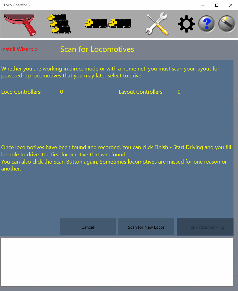
Figure 5 Install Wizard Page 5, here scan for new locomotives on your Home Net.
Any new locomotive or other WifiTrax controllers that have been installed, will have connected to your Home Net and an IP Address will have been assigned to them by your router. It is now necessary for Loco Operator to find out the IP Addresses and save each locomotive in its Database so that you can drive it whenever you start Loco Operator. Of course you do not need to go through this process every time! When you scan your net, you also detect Layout Controllers such as Switch Machine, Power and Lighting Controllers. These may be operated from the Drive Screen using the Layout Items Flyout.
Tap the "Scan for New Locos button" and wait for the scan to complete. Your new locos should appear in a new screen as shown below. Occassionally you may need to repeat the scan. If for some reason, they do not appear, try cycling their power (power down for 10 seconds and up again) as some of our earlier modules needed a power cycle.
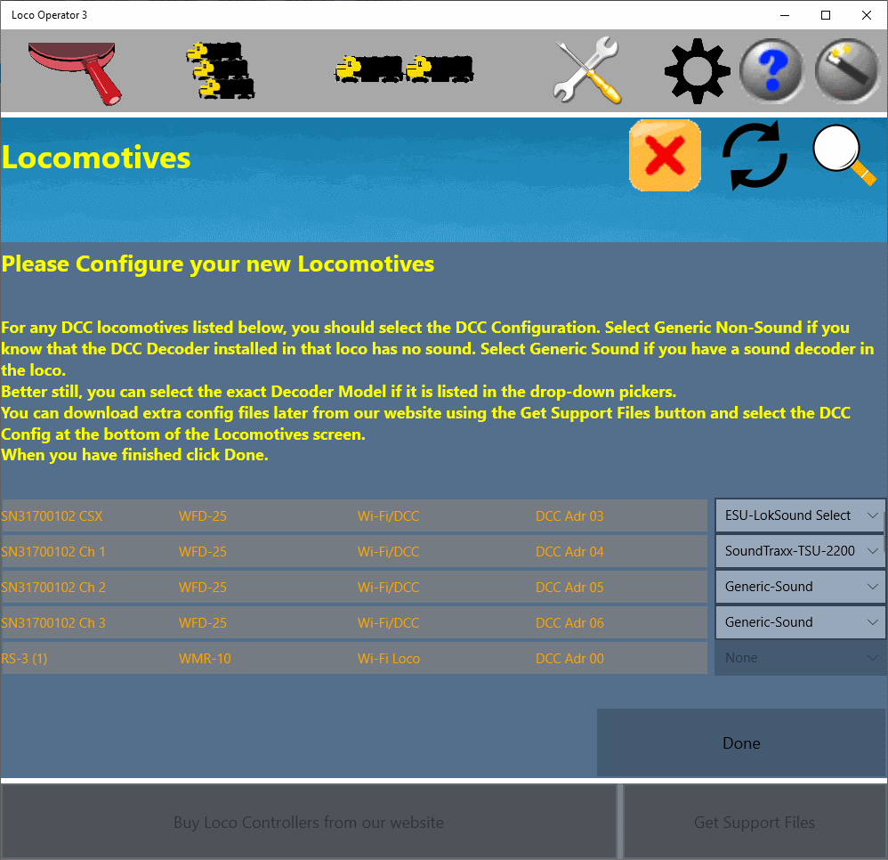
Figure 6 New locomotives appear after your Home Net has been scanned.
The figure above shows the results of the scan with five locomotives displayed. On Wizard page 4, in this example only two new controllers were installed but five locos were scanned on page 5. This is because one of the new controllers was a WFD-25 which defaults to 4 locomotive channels (16 can be configured). So each channel is shown as a separate locomotive.
Since the WFD-25 channels each drive a DCC locomotive, they have a DCC Address allocated whereas the WMR-10 shows zero. Also, the WFD-25 locomotive channels can be assigned a specific model of DCC Decoder to match the one installed in the locomotives that you intend those channels to control. You can select this in the drop-down selector at the end of each row.
When you are happy with the list, tap Done.
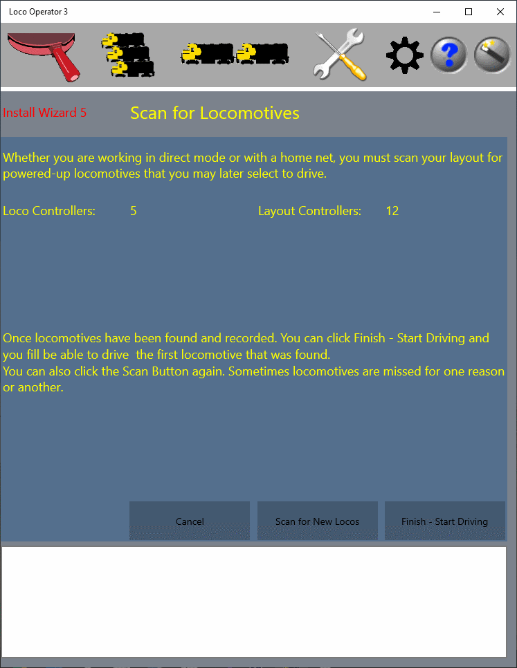
Figure 7 The Wizard page 5 shows total Locomotive and Layout Controllers.
The wizard page 5 then shows the total number of Locomotive Controllers now recorded in the system. If you have Layout Controllers such as Switch Machine Controllers, Lighting Controllers or Power Controllers, and are working in Infrastructure Mode with a Home Net, the number will also be displayed.
At this point, you can repeat the scan if for some reason one or more controllers were not found, you can tap Finish to exit the Wizard and display the Settings Screen or you can tap "Finish - Start Driving" which will take you straight to the Drive Screen with the first locomotive already selected.
Using the Install Wizard Later
You can re-enter the install wizard at any later time and change the Home Net details, Install new controllers and Scan for new controllers. You will be given a choice on page one as to whether you wish to change your Home Net. If you tap Yes, you will be able to change any aspect of it, including completely changing it to a different Wi-Fi access point. Usually you will not want to do that, but you may wish to correct something or change the IP Address range. Whether or not you change the Home Net, you will be given the opportunity to install any new controllers that are found. Finally you will be able to scan for any new locomotives or other controllers that have been installed on the Home Net.
If you change the Wi-Fi Access Point SSID or the Password, you will need to re-install all the locomotives or other controllers onto the new Home Net and then re-scan.
Networks
Central to the WifiTrax system of model railroad control is the concept of networks. We use this term to mean a collection of devices under control of a network router that may be accessed by the computer on which Loco Operator is installed. The devices on a network obtain their IP address from that router.
Network Scan
When you start Loco Operator for the first time, it will ask you to let it scan your device to see the networks that are accessible to it. For a tablet or phone device, these will usually be Wi-Fi networks that the device can connect to. You can repeat the scan at any time by tapping or clicking the "Scan Nets" button.
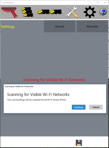
Figure 8 Network Scan
If you have installed on a desktop machine that has an Ethernet LAN adapter (network interface card) then that will appear as a network. On a typical laptop computer, you will probably have both an Ethernet LAN adapter and a Wi-Fi adapter, so both of these will appear as networks.
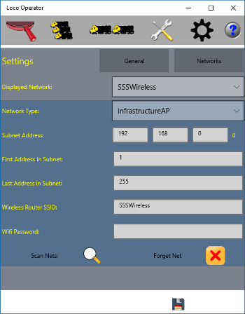
Figure 9 Networks Page
Networks are managed on the Settings tab towards the right at the top of the Loco Operator display. The Settings tab has two pages: General and Network. Networks are, of course managed on the Networks page of the Settings tab.
At the top of the Networks page, there is a Drop-down selector called Displayed Network. You can select any network here and the details will be shown in the blue section below. After you have scanned for networks, you will typically see a list including your Wi-Fi Access Point on your router, maybe a LAN network, some inaccessible access points for your neighbors and one or two beginning with "ESP_". These are the access points provided by your WifiTrax locomotive controllers, called Controller Networks. There may also be a Bluetooth network listed, which is not relevant to the App at this time. In the example the relevant networks are:
The Controller networks, beginning with ESP_, are networks provided by WifiTrax locomotives. On these networks, the locomotive is the access point and manages the network, acting as the DHP Server, handing out IP addresses to other computers connecting to it. It is its own Network Router, if you like. As well as managing its own network, the locomotive can also join another network as a station.
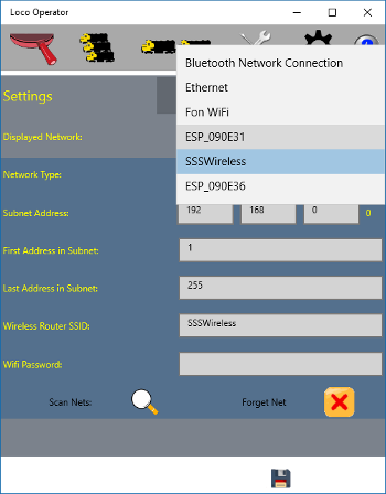
Figure 10 Typical Networks List
In the example, the following networks have been found:
- Bluetooth Network Connection - not relevant.
- Ethernet - the wired LAN to which this computer is connected.
- Fon WiFi - an inaccessible neighboring network.
- ESP_090E31 - a new WifiTrax-installed locomotive.
- SSSWireless - the infrastructure Wi-Fi network provided by the network router.
- ESP_090E36 - a new WifiTrax-installed locomotive.
Note that the last six digits of the locomotive Controller Networks are the last six digits of the AP MAC address printed on the label of the bag in which your WifiTrax controller module was shipped.
For each Infrastructure Network, a range of IP addresses can be reserved for WifiTrax controllers to use when acting as stations.
There are six pieces of information displayed when a network is selected.
- Network Type - Controller AP, Infrastructure AP or Wired LAN.
- Subnet Address - this must match the subnet of the DHCP controlling the network.
- First Address in Subnet - the first IP Address dedicated to WifiTrax controllers.
- Last Address in Subnet - the last IP Address dedicated to WifiTrax controllers.
- Wireless Router SSID - the SSID of the wireless access point of the network.
- Wifi Password - the password required for a station to connect to the network access point.
For a Controller AP, the subnet address will always be 192.168.4.0. For an infrastructure AP or Wired LAN, you must check the subnet address against your router, but it will default to the most common: 192.168.0.0.
For a Controller AP, the start and end address will always be 1, since there is only one controller on the network. For an infrastructure AP or Wired LAN, the range defaults to 1 - 255 but you should limit it to a smaller range and assign reserved IP addresses to your WifiTrax controllers. The range entered here is the range that will be scanned for locomotives. The IP addresses actually assigned wil be under control of your Network Router.
For a Controller Network, the Wireless Router SSID is defined by the WifiTrax module and is of the form ESP_XXYYZZ, where XX, YY and ZZ are the last three pairs of digits of the Station MAC (STA MAC) printed on the bag label of the WifiTrax module, e.g ESP_090E31 for a MAC address ending in -09-0E-31. For an infrastructure network, the SSID is that of your Wi-Fi access point. For a wired LAN network, it is not relevant.
The Wifi password is only needed, for an Infrastructure Network, if you want your controllers to act as stations on that infrastructure network. The password will be given to each controller so that it can connect to your protected infrastructure access point.
Network Re-Scan

You can re-scan your networks at any time by clicking or tapping the Scan Nets button existing networks known to the system will not be lost and any new ones will be added.

You can also remove a net from the system by selecting it in the Displayed Network drop-down and clicking the Forget Net button.
General Settings
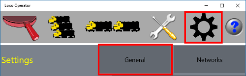
These are accessed from the General page of the Settings tab. Tap the settings tab first and then the General button.
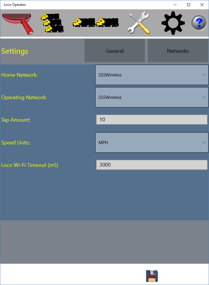
Figure 11 General Settings Page
Home Network
The first setting on the General Settings page is the Home Network. This is the Infrastructure Network that will be given to WifiTrax Locomotive Controllers for them to connect to as stations. All the locomotives that have been given this information will automatically connect to the home network and can then be controlled when that network is selected as the Operating Network - see below.
You must set up the IP Address range, SSID and Password for the network you choose as home using the Networks page as above. Also you must configure your network router to reserve IP Addresses within that range for the locomotive MAC Addresses. You only need to do this if you limit the IP Address range. You can leave it as 0 - 254, but scanning for locomotives will take a long time.
To give the Home Network information to each locomotive, you use the Tuning tab, see the Tuning section in thes pages.
Operating Network
The next setting on the General Settings page is the Operating Network. This is the Network that will be scanned when you use the Locomotives page and on which you can select locomotives for driving.
The operating network can be either an Infrastructure Network, a Wired LAN Network or a Controller Network. For example, if you have a new locomotive that has not yet joined the home network as a station, you can drive it on its own Controller Network by selecting that as the Operating Network. When you do this, you must connect your computer, tablet or phone to that network's access point using the Settings, Wi-Fi pages on the computer, tablet or phone that you are using.
In another example, you may want to use a Windows 10 desktop that has no Wi-Fi adaptor. Here you would choose your Wired LAN network as your operating network.
Once you have all your locomotives acting as stations on your Home Network, for a Wi-Fi accessible computer, tablet or phone, you will want to choose the Home Network as the Operating Network. Then you will be able to drive any single locomotive, drive two at a time and set up consists from that device.
Tap Amount
The tap amount setting on the General Settings page is the number of speed demand units by which the speed of a driven locomotive will be increased or decreased when the region above or below the thumb box on Speed lever is tapped. The speed demand is an integer between 0 and 1000. The increase or decrease is approximate.
This setting also governs the rate at which the speed will automatically increase or decrease when Auto Drive mode is selected. These features are fully described in the Driving tab section.
Speed Units
The speed units may be selected as MPH or KPH on this drop-down selector. This affects the appearance of all speedometers displayed.
Loco Wi-Fi Timeout
This setting determines the timeout in milli secconds that will be applied to all communications with a locomotive. If the locomotive does not respond during this time the communication will be considered to have failed. After two consecutive failures, the locomotive will be displayed as not responding and driving will no longer be possible. The locomotive will automatically stop after a period of time determined by its Contact Loss Stop Time (mS) described in the Tuning< section.
If a locomotive is determined as not responding, Loco Operator keeps trying to re-establish contact and if contact is re-established, driving may proceed as normal. However after a further period of time, the speed control will be set to zero for safety.
Locomotive Management
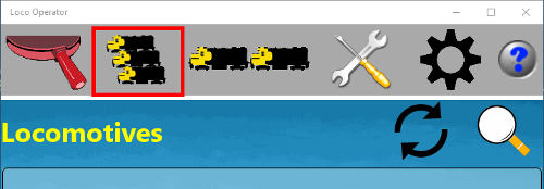
On the Locomotives tab, you can manage the locomotives that are present on your Operating Network. When you display this tab it will show the locomotives on the operating network that are already known to the Loco Operator app. Of course when you first use the App, there will be none.
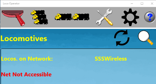
Figure 13 Accessibility Status of Operating Network
This tab also shows the accessability status of the Operating Network. The network will only be shown as accessible if your computer, tablet or phone is connected to the network. So if the network is shown as Not Accessible, you probably need to go to the Wi-Fi settings on your computer and connect to the network access point.

Once the network is accessible, you can cick the Scan button to scan the network for the locomotive controllers that are present.
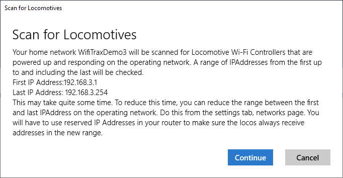
Figure 14 Full Subnet Locomotive Scan
The scan will take place over the range of IP addresses that you have defined for the network that is selected as the operating net. In the example shown, the range is the full range of the subnet. In this case the scan will take quite a long time. You can reduce this time by limiting the IP range of the network on the Settings tab, Networks page, but you must make sure that the router will assign IP addresses to the locomotives within this range. You can do this by assigning reserved addresses to the locomotive controller MAC addresses in your router.
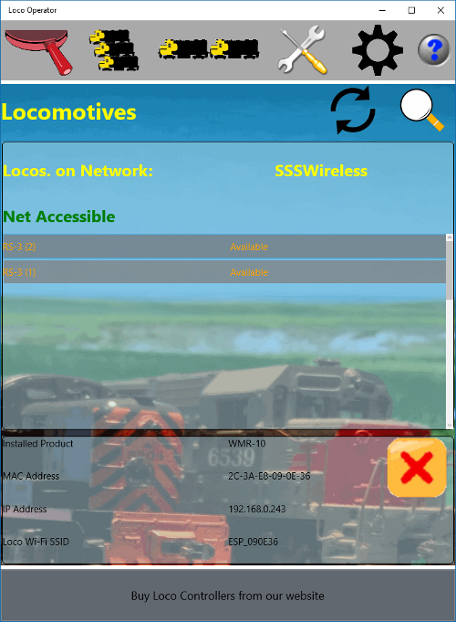
Figure 15 Locomotives Screen after Completion of a Scan
Once the scan is complete, you will see a list of the locomotives that have been discovered on the operating network. You can repeat the scan at any time. New locomotives will be added and existing ones updated but existing locomotives that are no longer visible (because they are powered down or off the track) will not be removed.
As well as the accessibility of the network, this page also shows the availability of each locomotive on it. Any that have been discovered in the latest scan will be available, but older ones may be unavailable if they are now powered down or removed from the track.
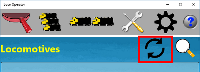
You can update the accessibility display of the operating net and the availability of the displayed locos by clicking or tapping the Update button. If you have removed a locomotive from the track and replaced it since you viewed the Locomotives tab, you should update with this button.
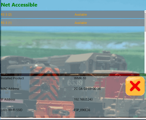
Figure 16 Locomotive Details
When you select a locomotive in the list by clicking or tapping it, its details are shown in the panel at the bottom of the screen The information shown here is:
- Installed Product - The installed WifiTrax product in the locomotive such as WMR-10, WMH-20.
- MAC Address - The station MAC address of the locomotive controller.
- IP Address - The IP address of the locomotive controller, as assigned by the DHCP server (i.e. the router) on the operating network.
- Loco Wi-Fi SSID - The SSID of its Controller Network Access Point.
- Direct Sound to: - A layout sound source to which the locomotive sound output is to be directed (Not yet implemented).
- DCC Configuration: - The DCC Decoder Model installed in the locomotive. This is applicable only to locos operating under Wi-Fi DCC Technology.
DCC Decoder Model Selection
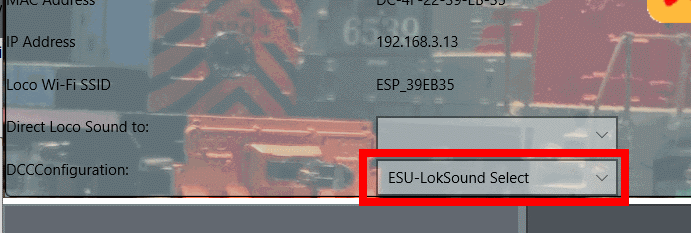
Figure 17 DCC Configuration Drop-Down Selector
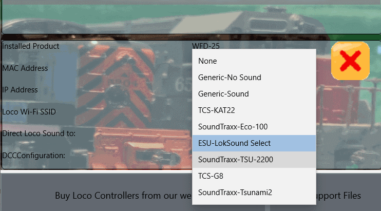
Figure 18 Selecting the DCC Configuration - for Wi-Fi/DCC Locomotive only
When you drive a Wi-Fi/DCC locomotive a set of named function buttons will be displayed such as Lights, Bell, Horn etc. The buttons that are displayed depend on the model of DCC decoder that you have selected. For instance, if you have a sound decoder, you will need to have more buttons here than for a non-sound decoder. Also different manufacturers attach different sounds to the functions. You can select the decoder model that you have installed in the selected locomotive in the DCC Configuration drop-down selector shown in Figure 17.
Loco Operator ships with a set of in-built configurations for common decoders. If yours is not selected, you can select "Generic Sound" or "Generic Non-Sound". You can also use the "Get Support Files" button to download the available DCC configuration files which you can modify as needed.
To make your own DCC Configuration File, you must be connected to the internet, then:
(1) Click the "Download Support Files" button at the bottom-right of the Locomotives screen. This will open a browser window
that lists types of support files,
(2) Click the "DCC Configuration Files" hyperlink,
(3) Click the "Generic.dcg" file and save it to a suitable location on your computer,
(4) Open it in a suitable editor such as Notepad (on Windows) and modify it as needed. Give the file a unique name with file extension ".dcg" such as "MyDecoder.dcg".
Then save it to the LocalState folder of the Loco Operator 3 App. This is:
C:\Users\<Your User Name>\AppData\Local\Packages\STEVESHRIMPTONSCIENCESPTY.LocoOperator3_69daas6km4m3j\LocalState.
on Windows or the Downloads folder on Android.
Note: If your file is invalid, Loco Operator may crash on start-up. If this happens, simple remove your .dcg file to some other location until you have fixed it.
When you edit this file you can duplicate the DccFunctionM elements, making sure each one has a different value for its DccFunction element. the IsSpecial element value of 1 means that a function button will be displayed on the Named DCC Functions panel. If you copy the file to make more than one customised DCC Configuration, you MUST change the value of the DccConfigUuid element. This must contain exactly 32 upper-case hexadecimal characters. You can probably get away with just changing one or two. If you want to be correct use an on-line Guid generator, remove the dashes (-) and change everything to upper case.
Sorry if this is too technical, we will try to add these features in a more user-friendly way in a later version of Loco Operator.
Removing Locomotives
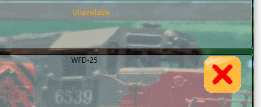
Figure 19 Loco Remove Button
You can remove a locomotive from the record by selecting it in the list and clicking or tapping the remove button in Figure 19. You can always add the locomotive back by powering it up and repeating the scan.
Figure 20 Loco Clear Button
You can remove all the locomotives from your local database record using the Loco Clear button in Figure 20.
Driving
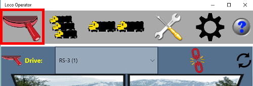
Figure 21 Driving Tab that displays the Drive Screen
Select the Driving tab so that you can choose a locomotive to drive. You must select a locomotive on the driving tab if you want to drive it and also if you want to adjust its configuration variables on the tuning tab.
Selecting the Locomotive
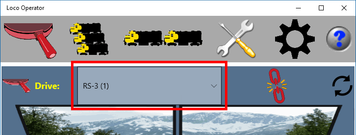
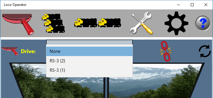
Figure 22 The Locomotive Drive Selector
Use the locomotive "Drive:" drop-down selector in Figure 22 to select the locomotive that you want to drive. Only available locomotives are listed. Use the Update button
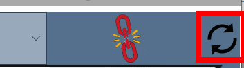
Figure 23 The Drive Availability Update Button
Use the Update button in Figure 23 to update the available locomotives if you have powered new ones up or reconnected your computer or tablet to your operating network.
Wi-Fi Loco, Wi-Fi/DCC and Wi-Fi DC Loco Technologies
WifiTrax provides three kinds of Wi-Fi Locomotive Control Technologies: Wi-Fi Loco, Wi-Fi/DCC and Wi-Fi DC. Loco Operator may be used to drive locomotives operating under either of these three methods of control. In fact a single installation of Loco Operator can control two locomotives at a time that may be operating under different technolgies. The Drive Screen will be configured differently for DCC without speedometer display, but with named DCC function buttons and the option to open a DCC keypad. For DCC, the Tunings Screen will also be different.
Locomotives fitted with Wi-Fi Loco technology have WifiTrax modules such as WMH-20 or WMR-10 installed and are controlled directly from Wi-Fi.
Locomotives operating with Wi-Fi/DCC technology have DCC Decoders installed and either also contain Wi-Fi/Loco interface modules (such as WDMI-24, WDMI-35 or WDMI-51), or are operating on track powered by a Wi-Fi/DCC Trackside module such as WFD-25.
Locomotives operating with Wi-Fi DC technology are operating on track powered by a Wi-Fi DC Trackside module such as WUFP-47.
Loco Operator can also be used to select certain "Non-Drivable" modules (such as WDMI-61 DCCIP Send Module), but only to allow their Tunings to be adjusted.
Control of Locomotive Lights (Wi-Fi Loco and Wi-Fi DC Technology only)
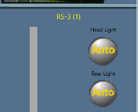
Figure 24 The Locomotive Light Controls
The Wi-Fi Loco products from WifiTrax provide control of the front and rear lights of the locomotive. Each of these may be in three states: Off, On and Auto. Off means the light is always off, On means it is always on and Auto means that the front or rear light will come on if the locomotive is driven in that direction. Tap or click the buttons to move through the three states. The lights can be changed while the locomotive is in motion.
Control of Locomotive Direction (All Loco Technologies)
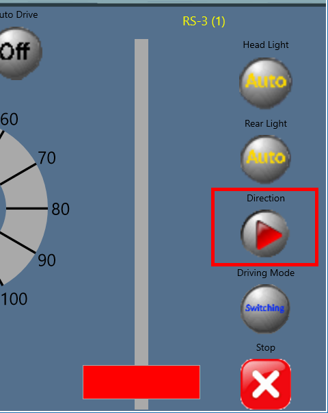
Figure 25 The Locomotive Direction Button
Tapping the Direction button switches between forward and backwards. The direction button is disabled while the locomotive is in motion. For a multiple unit consist, the direction button applies to the entire consist. It will take into account that some locomotives are facing backwards provided those locos have been set with reverse direction on the consist tab.
Locomotive Driving Mode (All Loco Technologies)
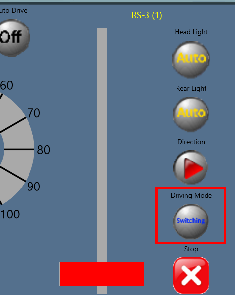
Figure 26 The Driving Mode Button Button
The Driving Mode button can be set to Switching or Main Line. In Switching mode it is possible to control the locomotive more precisely at low speed and the top speed is limited to about 15 MPH. In Main Line mode, the top speed is as fast as the locomotive can go but there is still a non-linear response at low speeds to allow for smooth take-offs.
Stop Locomotive (All Loco Technologies)
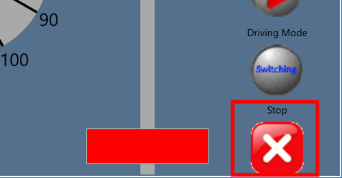
Figure 27 The Stop Button
The locomotive can be stopped immediately by clicking or tapping the stop button. The stop button can be used any time. There may be a delay of about a second before the command reaches the locomotive due to network delay. The locomotive will also take time to stop due to its physical momentum - i.e. the momentum of its flywheels and body mass.
Speed Control (All Loco Technologies)
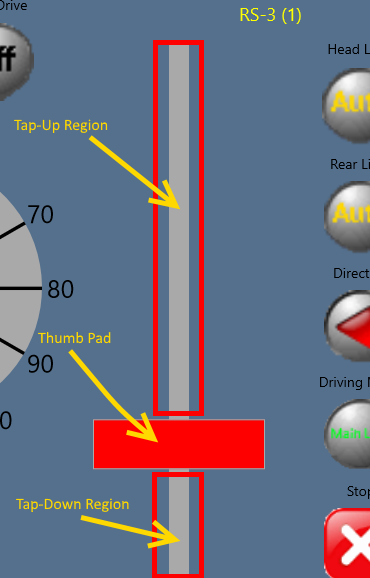
Figure 28 The Speed Lever
The speed of the locomotive is controlled by the Speed Lever. There are two modes of use. With Auto Drive turned off, the speed of the locomotive can be changed by sliding the thumb pad up or down. If the thumb pad is moved fully down, the locomotive will stop completely. As explained in the Locomotive Driving Mode section, the maximum speed will be governed by whether the locomotive is set to Switching or Main Line.
Tapping the region above or below the thumb pad will cause the speed to be increased or decreased by an amount determined by the Tap Amount setting in the General page of the Settings tab.
Auto Drive (All Loco Technologies)
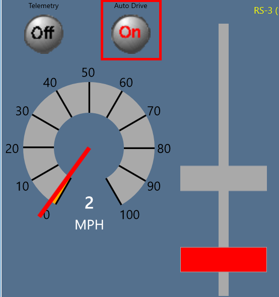
Figure 29 The Auto-Drive Button
Auto Drive is a simple feature that allows you to initiate a smooth change of speed of the locomotive. It is turned on or off by clicking or tapping the Auto Drive button. If you turn Auto Drive on, you can tap or click anywhere on the Tap-Up or Tap-Down region on the Speed Lever and, instead of causing an incremental speed increase, the tap will cause a Target Rectangle to appear at the location of the tap. The speed of the locomotive will then gradually increase or decrease towards the target speed. Once the target speed has been reached, the locomotive will stay at that speed. If you tap right at the bottom of the Tap-Down region the locomotive will slow down and stop. The rate at which the locomotive accelerates or decelerates is determined by the Tap Amount setting on the General Page of the Settings tab. The higher the Tap Amount, the greater the acceleration or deceleration.
If you wish to take manual control of the locomotive before the Auto Drive action is complete, simply touch or move the thumb pad on the speed lever. Turning off Auto Drive will also end the Auto Drive action. You may turn Auto Drive on or off while the locomotive is in motion.
Speedometer (Wi-Fi Loco and Wi-Fi DC Technology only)
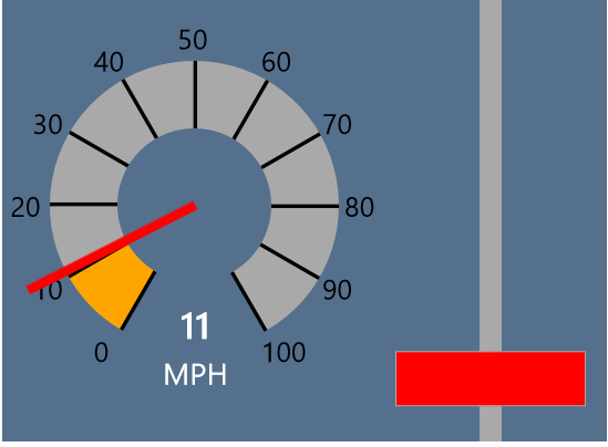
Figure 30 The Speedometer
The speedometer shows the approximate speed the locomotive is moving in either Miles per Hour (MPH) or Kilometers per Hour. The speed is obtained from the back e.m.f. generated by the motor, passed through a calibration table to give the speed. The accuracy will depend on the characteristics of the locomotive motor and has been set at the factory for a typical high quality motor such as those fitted in most new locomotives. We intend to allow the user to adjust this in a later version of this App as part of the tuning process. You can select MPH or KPH on the General page of the Settings tab.
Telemetry (Wi-Fi Loco and Wi-Fi DC Technology only)
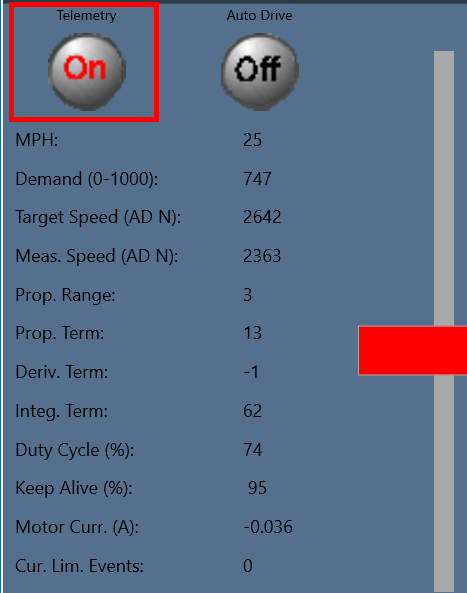
Figure 31 The Telemetry Display
You can switch between Speedometer display and Telemetry display by clicking or tapping the Telemetry button. When the Telemetry display is visible, it shows the following information which is an indication of how your locomotive is performing:
- MPH - The speed in Miles per Hour
- Demand - The requested speed being sent to the locomotive from this App. The demand is like a speed step and is in the range 0 - 1000. So the WifiTrax system provides a granularity of one part in a thousand - more than you would ever need.
- Target Speed - The target speed that the locomotive firmware calculates from the demand. The units are AD N, which is an integer count ranging from 0 to 4095. For the technical, this is the required output from the 12-bit A/D Converter converting the motor's back e.m.f to a number N.
- Measured Speed - The actual speed of the locomotive as measured at the A/D e.m.f. coverter. The units are AD N, which is an integer count ranging from 0 to 4095. For the technical, this is the actual output from the 12-bit A/D Converter converting the motor's back e.m.f to a number N.
- Proportional Range - The speed control algorithm has a feedback term that is proportional to the error between the Target and Measured speed. The amount is different according to one of three speed ranges (1, 2 and 3). This figure shows the range in which the speed control is operating in.
- Proportional Term - The actual value of the proportional control term generated from the error between the target and measured speed.
- Derivative Term - The speed control algorithm also uses a derivative term, which depends on the rate of change of the error.
- Integral Term - The speed control algorithm also uses an integral term. The purpose of this is to gradually include a fixed error correcting amount so that the proportional term will reduce to zero.
- Duty Cycle - The duty cycle of the pulse width modulated current passing through the motor. When this is 100%, the locomotive can go no faster.
- Keep Alive - The percentage of full voltage available from the power maintenance capacitors. This will drop if you go over dirty track.
- Motor Current - The average current passing through the motor, measured in Amperes.
- Current Limit Events - A number representing the number of times the current has been limited during approximately the last second. Current limiting is a feature available as part of the locomotive tuning.
DCC Named Function Buttons (Wi-Fi/DCC Technology Only)
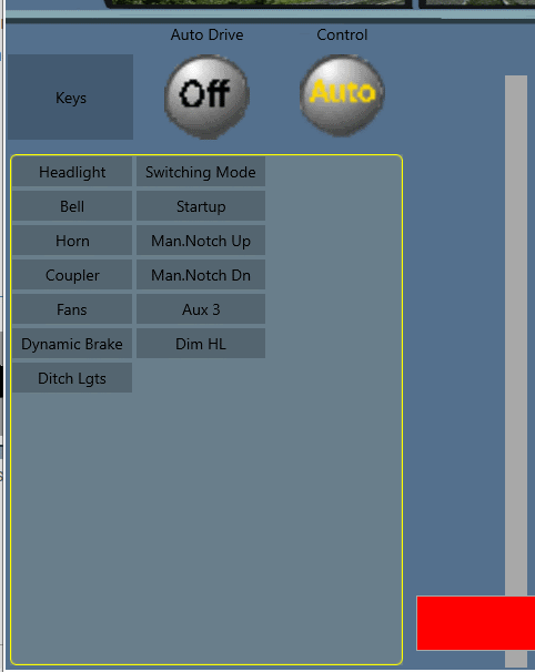
Figure 32 Named DCC Function Buttons
The DCC named function buttons appear when DCC locomotives are being driven. The buttons displayed depend on the model of DCC decoder selected as being that installed in the loco. You select the decoder model either after the scan process or at any time on the Locomotives screen The buttons operate either latching or momentarily according to their definition for the DCC decoder chosen. When Latched, the text within the button shows red.
The Keys button above this display allows entry to the DCC Keypad, which is only accessible in Single Driving Mode.
DCC Keypad (Wi-Fi/DCC Technology Only)
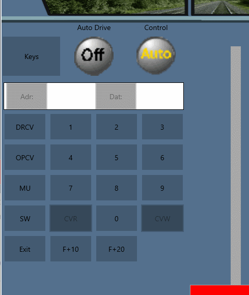
Figure 33 DCC Keypad in Function Mode
The DCC Keypad is displayed by tapping the Keys button above the DCC Named Function Buttons and displays as a numeric keypad with various modes of operation. It defaults to the Function mode where each key acts in the same way as a DCC function key on a DCC Command Station. You can select F + 10 and F + 20 mode to send DCC function values higher than 0 - 9. Not all WifiTrax modules support higher than 12.
DCC Operational Mode CV Programming (Wi-Fi/DCC Technology Only)
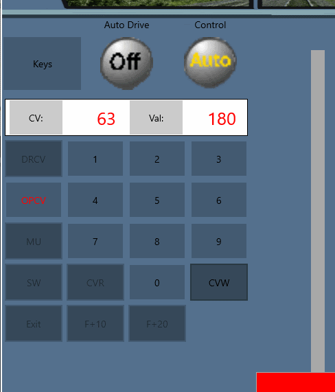
Figure 34 DCC Keypad in Operational CV Programming Mode
Operational Mode Programming is entered from the DCC Keypad by tapping the OPCV button. Once Operational Mode Programming is entered this button glows red. In Operation Programming Mode you can program CVs "on the main line" via the NMRA DCC "Configuration Variable Access - Long Form" protocol. This allows writing of CV values but most DCC decoders do not allow read-back of CVs in this mode and WifiTrax modules do not currently support it. The bottom line is that you can only write CVs in this mode. DO NOT TRY TO WRITE THE ADDRESS CV (CV #1) IN THIS MODE.
To write a CV:
(1) Tap on the "CV:" button at the top left of the DCC keypad. This clears the CV number textbox to the right of the "CV:" button,
(2) Tap on the numeric keys to supply the CV number required. This is shown in the CV number textbox,
(3) When the CV number is correct, tap on the "Val:" button. This will clear the CV value textbox to the right of the "Val:" button,
(4) Tap on the numeric keys to supply the CV value required. This is shown in the CV value textbox,
(5) Tap the CVW button. A warning dialog will appear. Tap Continue and the new CV value will be written, the value will NOT be read back for confirmation.
DCC Direct Mode CV Programming (Wi-Fi/DCC Technology Only)
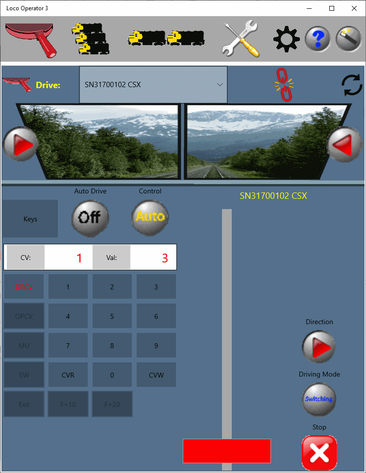
Figure 35 DCC Keypad in Direct CV Programming Mode
Direct Mode Programming is entered from the DCC Keypad by tapping the DRCV button. Once Direct Mode Programming is entered, this button glows red. Direct Mode Programming can only be used when there is only one DCC decoder connected to the outputs of the Wi-Fi/DCC module that is being driven and programmed. For example Direct Mode Programming can always be used for a loco-mounted Wi-Fi/DCC interface such as WDMI-24, WDMI-35 and the motherboards WDMI-51/52. However for a Trackside Wi-Fi/DCC Interface such as the WFD-25, Direct Mode Programming can only occur on its Programming Track outputs. Direct Mode Programming is implemented using the NMRA DCC Service Mode Programming protocol.
Once Direct Mode Programming is active, CVs can be read as well as written. For example, in the figure, the CV number 1 has been read to display the DCC decoder's DCC address which is shown to be 3.
To read a CV:
(1) Tap on the "CV:" button at the top left of the DCC keypad. This clears the CV number textbox,
(2) Tap on the numeric keys to supply the CV number required. This is shown in the CV textbox,
(3) When the CV number is correct, tap on the CVR button. This will read the existing value of the CV from the decoder and display it in the
"Val:" textbox."
To write a CV either continue from the read operation or repeat steps (1) and (2), then:
(4) Tap on the Val button. This will clear the Val: textbox,
(5) Tap on the numeric keys to supply the CV value required. This is shown in the Val textbox,
(6) Tap the CVW button. A warning dialog will appear. Tap Continue and the new CV value will be written, then read back and displayed
for confirmation.
To exit Direct Mode Programming, tap the DRCV button which will change to black, showing that the programming mode has been exited.
DCC Accessory Operation (Wi-Fi/DCC Technology Only)
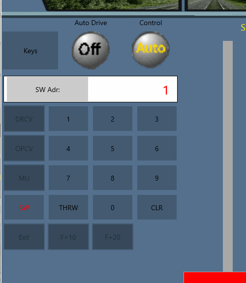
Figure 36 DCC Keypad in Accessory Mode
Accessory Mode is entered by tapping the SW button which will change to read indicating that Accessory Mode is active. Accessories can be operated that are connected to the Main Track DCC output of a Trackside Wi-Fi/DCC module such as the WFD-25. Connected accessories are additional to the sixteen DCC addressed locos that can be included in the WFD-25 roster and their DCC address space does not overlap with that of locomotives.
Once Accessory Mode is active, switches or other accessories can be operated by using the following sequence.
(1) Tap on the "SW Adr:" button at the top left of the DCC keypad. This clears the Accessory Address textbox to the right of the "SW Adr:" button,
(2) Tap on the numeric keys to supply the Accessory Address required. This is shown in the the Accessory Address textbox,
(3) When the Accessory Address is correct, tap on either the THRW or CLR button. This will throw or clear a switch machine connected as an accessory. Other kinds of accessory will
interpret the THRW or CLR instruction in a manner dependent on their design.
To exit Accessory Mode, tap the SW button which will change to black, showing that the Accessory Mode has been exited.
Dual Driving Mode (All Loco Technologies)
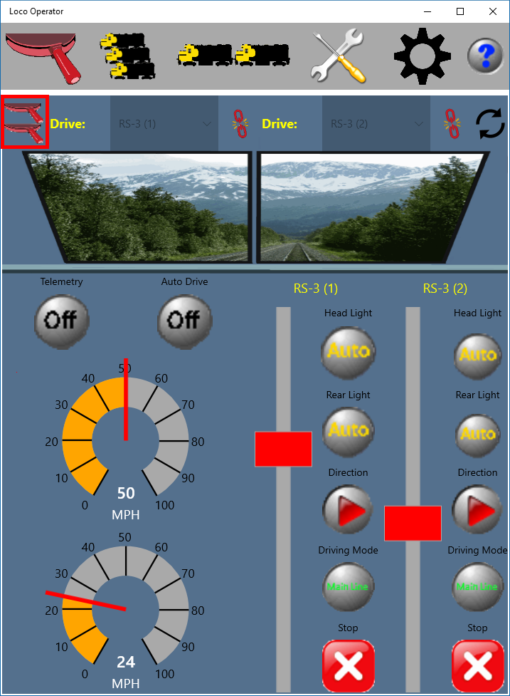
Figure 37 Dual Driving Mode
When the Driving tab is displayed, you can switch between single and dual mode as needed using the Single/Dual button outlined above. Tap or click once to go to dual mode, then tap or click again to go back to single mode. The part of the screen assigned to each loco will be configured according to the Loco Technology under which that loco is operating. For instance for Wi-Fi/DCC, the speedometer will be absent and the DCC function buttons displayed instead.
When in dual mode, the driving controls are duplicated, including the locomotive selector. You can select a different locomotive for each set of controls and drive them at the same time. There is no restriction on your choice of locomotive except that you cannot choose the same locomotive for both sets of controls.
The selection on either or both sides can be a multiple unit consist, so you can drive two consists at the same time if you wish.
One restriction is imposed for safety: You cannot go back to single mode if you have a locomotive selected for driving in the right-hand set of controls. You must deselect the right hand locomotive first. You can switch from single to dual mode while driving a locomotive with the left-hand set of controls. So you can switch to dual, drive a loco with the right-hand controls for a while, then switch back to single while continuing to drive with the left hand controls all the time.
In Dual Driving Mode, the setting of the Auto Drive button applies to both sets of controls. You can initiate Auto Drive speed changes independently but you cannot tap up or down on one while using Auto Drive on the other.
Tuning
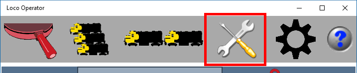
Figure 38 Clicking the Tuning Tab displays the Tuning Screen
Select the Tuning tab to adjust configuration variables that govern your locomotives's behavior, but first you must go to the Driving tab, make sure it is in single driving mode and select a Locomotive.
Screen Layout
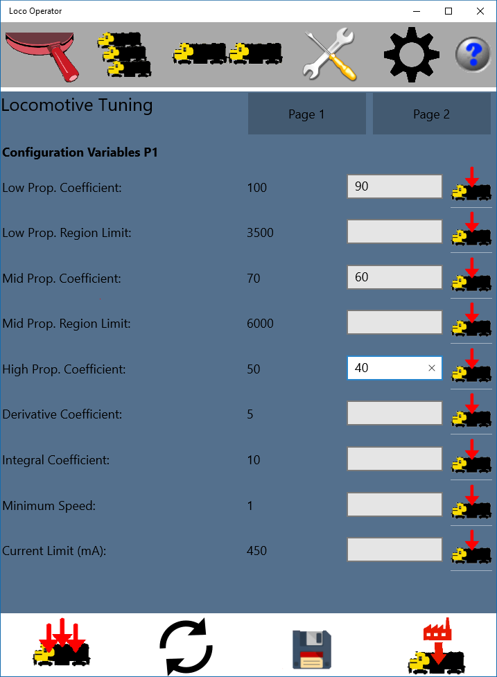
Figure 39 Page 1 of the Tuning Screen
Select the Tuning tab to adjust configuration variables that govern your locomotives's behavior, but first you must go to the Driving tab, make sure it is in single driving mode and select a Locomotive. There are two pages Page 1 and Page 2. You can select one of these using the buttons at the top right of the display. The figure above shows Page 1.
Each page has four columns: The name of the Configuration Variable, the present value as returned from the locomotive, a column of Text Boxes in which new values may be entered and a column of buttons. Clicking or tapping one of these buttons sends the new value of only that configuration variable to the locomotive.
At the bottom of the screen there are four buttons which are described below.
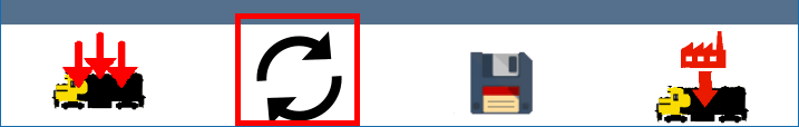
Figure 40 Tuning Screen Refresh Button
This button refreshes the displayed values displayed on the second column, that are currently in the locomotive.
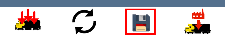
Figure 41 Tuning Screen Make Permanent Button
This button saves the values that are in the locomotive to the Flash memory in the locomotive. This means that they will not be lost when the locomotive is powered down.
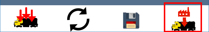
Figure 42 Tuning Screen Restore Factory Settings Button
This restores all of the tuning configuration variables in the locomotive to their default factory set values. Any changes that you have made will be lost.
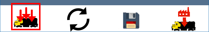
Figure 43 Tuning Screen Save All Button
This saves all of the configuration variables whose values have been changed to the locomotive. You still have to click the make permanent button to make the changes remain after power is cycled.
Page One Configuration Variables
The configuration variables that can be modified on Page One of the tuning tab are:
- Low Proportional Coefficient - The muliplier for the speed error used for the proportional feedback term in the speed control algorithm within the Low Range.
- Low Region Limit - The boundary between the Low Proportional Zone and the Mid Proportional Zone in the Speed Control Algorithm. The units are AD N, i.e. Analog to Digital Converter counts.
- Mid. Proportional Coefficient - The muliplier for the speed error used for the proportional feedback term in the speed control algorithm within the Middle Range.
- Mid. Region Limit - The boundary between the Mid Proportional Zone and the High Proportional Zone in the Speed Control Algorithm. The units are AD N, i.e. Analog to Digital Converter counts.
- High Proportional Coefficient - The muliplier for the speed error used for the proportional feedback term in the speed control algorithm within the High Range.
- Derivative Coefficient - The muliplier for the speed error used for the derivative feedback term in the speed control algorithm within the Middle Range and High Ranges. The derivative term is not applicable in the low range.
- Integral Coefficient - The muliplier for the speed error used for the integral feedback term in the speed control algorithm over all ranges.li>
- Minimum Speed - The minimum speed your locomotive can sustain. When you start your locomotive it will always begin at this speed.
- Current Limit - The motor current in amperes at which limiting will begin. If this is set to zero, current limit will be turned off. In this case the unit, or your locomotive may overheat. Curren will be permitted above this limit for 0.5 seconds to allow large currents that may be needed for the speed control algorithm to start the motor.
Page Two Configuration Variables
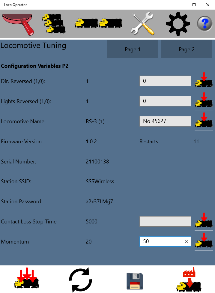
Figure 44 Page two Tuning Configuration Variables
The configuration variables that can be modified on Page Two of the tuning tab are:
- Direction Reversed - 0 or 1 will reverse direction of travel of the locomotive according to the Direction driving control. You can change this if the motor connections happen to be reversed.
- Lights Reversed - 0 or 1 will reverse direction of front and rear lights of the locomotive according. You can change this if the front and rear lights happen to have been wired to the wrong connections. The LEDs MUST still be wired the correct way around however or they will not come on.
- Locomotive Name - A name that you may choose for your locomotive.
- Station SSID - The SSID of the Access Point of the home network. The home network is the network to which the loco will connect as a station. This is populated automatically from the settings information on the Networks page of the Settings tab for the network chosen as the home network. The Home network is chosen on the General page of the Settings tab.
- Station Password - The password for the Access Point of the home network. This is populated automatically from the settings information on the Networks page of the Settings tab for the network chosen as the home network. The Home network is chosen on the General page of the Settings tab.
- Contact Loss Stop Time - This is the time, in milliseconds that the locomotive will continue moving after it has lost contact with the computer, tablet or phone running this App.
- Momentum - This is an arbitrary number that simulates inertia meaning that the locomotive will take time to respond to the Speed lever setting. The default is 20 which gives a smooth operation without adding very much inertia. You can increase or decrease this a little as required.
Multiple Unit Consists
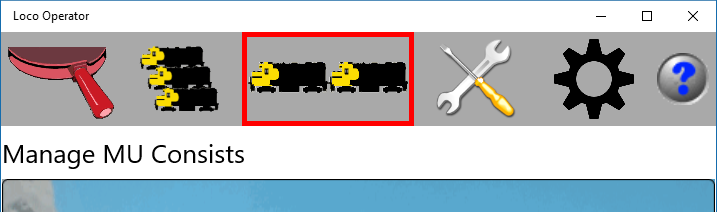
Figure 45 Tapping the Consists Tab displays the Consists Screen
Select the Consists tab to define groups of locomotives to be driven together as Multiple Unit Consists. Any number of such consists may be defined each containing any number of locomotives. A consist is a definition of an instance of multiple unit operation which may not always be active. A consist is only active when all of its units are coupled, in which case the locomotives cannot be driven independently. Thus a locomotive may be included in any number of consists but only one can be active at any given time.
This versatile arrangement lets you define your consists in advance with the tuning adjusted for best performance. Then when you assemble a consist for driving, you simply set all the locomotives in the consist to coupled and you may drive the consist.
Creating and Naming a New Multiple Unit Consist
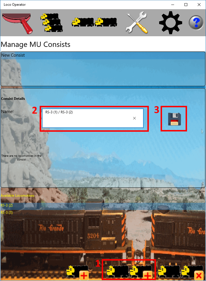
Figure 46 Creating a New Multi-Unit Consist on the Consists Screen
To create a new multi unit consist, first click the New Consist button (1 in the diagram). The consist will be created and given a default
name.
Then replace the default name with the name that you want (2 in the diagram).
Finally click the Save button (3 in the diagram)
to save the name change.
Your new consist will appear in the list of consists. If you select it, information about it will be shown in the details section including a list of locomotives included and the settings for each locomotive as a part of the consist.
Adding Locomotives to a New Multiple Unit Consist
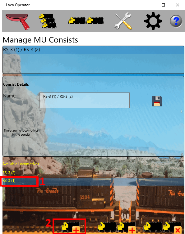
Figure 47 Adding a Locomotive to a Multi-Unit Consist
Once you have created and named your new consist, you need to add locomotives to it. You do this by first selecting the locomotive that you want by selecting it in the Available Locomotives List (1 in the diagram). Then you click the Add Locomotive button (2 in the diagram). Repeat this process until you have added those that you require in the consist. Don't worry if you add them in the wrong order, you can change the order later.
See the Details each Locomotive within a Consist
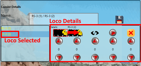
Figure 48 Details of a Locomotive in a Multi-Unit Consist
When you have added the locomotives, the consist detail will show the list of locomotives on the left. The details of the locomotive are shown to the right of the list for a selected locomotive.
Set the Direction of Locomotives within a Consist
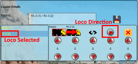
Figure 49 Direction of a Locomotive in a Multi-Unit Consist
Within the Loco Details section of the consist for a selected locomotive, there are many adjustments. One is the direction shown above. If the loco is to be facing backwards in the consist, tap or click the direction button so that it points to the left. The direction of travel of that locomotive will then be opposite to the direction of the consist. The rear light will also take the place of the front light for the lights in the consist. If the front light of the consist is turned to on, the backward facing locomotive will have its rear light on with equivalent behavior for the rear light of the consist.
Adjusting the Order of Locomotives within a Consist
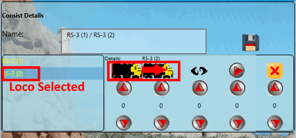
Figure 50 Position of a Locomotive in a Multi-Unit Consist
To adjust the order of the locomotives in a consist, you can select any locomotive, then tap the Move Forward button to move it forward one place.
Removing Locomotives from a Consist
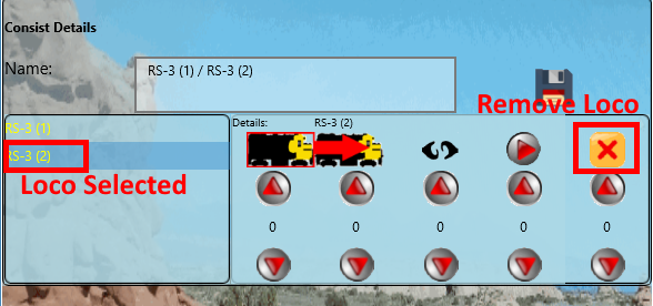
Figure 51 Removing a Locomotive from a Multi-Unit Consist
To remove a locomotive from a consist, select the locomotive and click the remove button.
Coupling the Locomotives
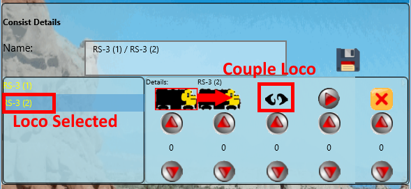
Figure 52 Coupling a Locomotive into a Multi-Unit Consist
As has been explained earlier, consists can be defined but the locomotives may not be assembled into them. They may be assembled as part of another consist or they may be being driven separately. When the locomotive is coupled in a consist in which it is a member, the locomotive may not be driven separately. Only when at least two consecutive locomotives in a consist are coupled can the consist be driven. This may be required when assembling a consist so that a third locomotive and the partially assembled consist can be driven towards each other.
Of course, just because the loco is marked as coupled does not mean it is physically coupled. That's up to you. In fact when you are tuning a consist to match the speeds of the locomotives, you will want to mark them as coupled but have them physically uncoupled so that you can see if the gap remains approximately constant.
To couple a locomotive, select the locomotive and tap the Couple button. It will change to indicate that the couplings are connected.
Tuning the Consist
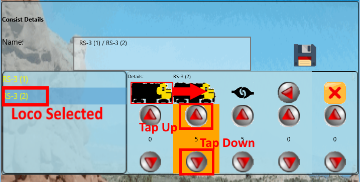
Figure 53 Tuning a Locomotive in a Multi-Unit Consist
The Loco Operator App provides comprehensive facilities to match the speeds of locomotives in a consist over their speed range.
To match the speeds of the locomotives in the consist, you can drive a pair of the locos marked as coupled but physically uncoupled and a short distance apart. You can run the consist at several speeds and use the Tap Up and Tap Down buttons to increase or decrease the speed of a loco in the consist by 5 speed units relative to the consist. The orange rectangle in the diagram indicates which speed range the loco is in, so you know which tap up/down buttons to use.