
ONLINE HELP
These help pages apply to version 2.0 release of Tower Operator. Please upgrade as new versions become available.
Getting Started
This online help is intended as a Tower Operator reference and is quite complicated in places. In order to get your model railroad Wi-Fi network up and running with the minimum effort, it is recommended that the Tower Operator First Steps document first be followed:
http://www.wifitrax.com/appNotes/quickStart/Tower-Operator-Quick-Start.pdfThis takes you through the steps of:
- 1. Getting your controller working in Direct Wi-Fi mode.
- 2. Creating a Test Control Panel and Verifying Operation.
You can then use the entire Wi-Fi Layout Quick Start document at:
http://www.wifitrax.com/appNotes/WifiLayout-Quick-Start.pdf
which also contains both module and app guidline and will help you go further to:
- 1. Set up your infrastructure model railroad network and switch your controller(s) over to behave as stations on your infrastructure Wi-Fi network.
- 2. Build a more complex Schematic Control Panel.
You can also read about networking with WifiTrax in the document Managing your Model Railroad Network
http://www.wifitrax.com/appNotes/Managing-your-Model-Railroad-Wi-Fi-Network.pdf
Wi-Fi Network Management
Central to the WifiTrax system of model railroad control is the concept of networks. We use this term to mean a collection of devices under control of a network router that may be accessed by the computer on which Tower Operator is installed. The devices on a network obtain their IP address from that router.
Network Scan
When you start Tower Operator for the first time, it will ask you to let it scan your device to see the networks that are accessible to it. For a tablet or phone device, these will usually be Wi-Fi networks that the device can connect to. You can repeat the scan at any time by tapping or clicking the "Scan Nets" button.
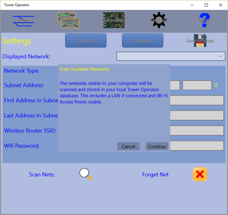
Figure 1 Network Scan
If you have installed on a desktop machine that has an Ethernet LAN adapter (network interface card) then that will appear as a network. On a typical laptop computer, you will probably have both an Ethernet LAN adapter and a Wi-Fi adapter, so both of these will appear as networks.
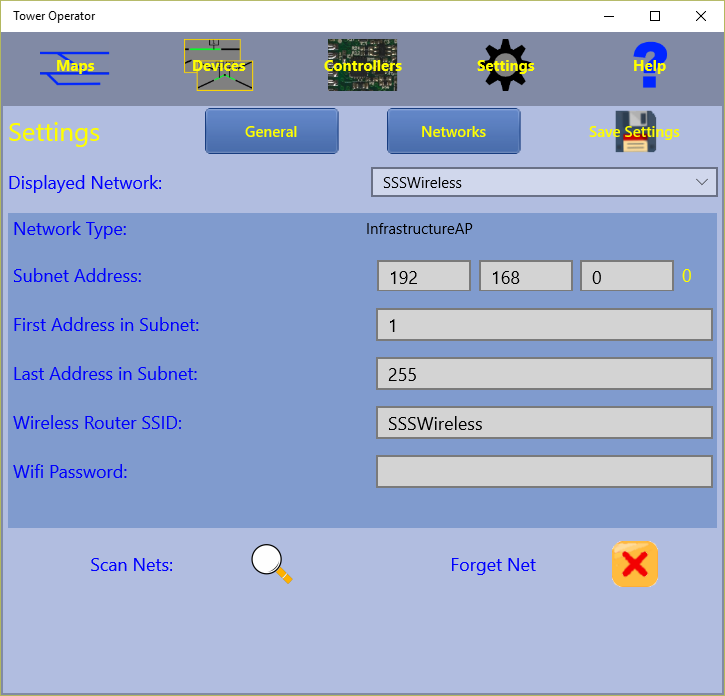
Figure 2 Networks Page
Networks are managed on the Settings tab towards the right at the top of the Tower Operator display. The Settings tab has two pages: General and Network. Networks are, of course managed on the Networks page of the Settings tab.
At the top of the Networks page, there is a Drop-down selector called Displayed Network. You can select any network here and the details will be shown in the darker blue section below. After you have scanned for networks, you will typically see a list including your Wi-Fi Access Point on your router, maybe a LAN network, some inaccessible access points for your neighbors and one or two beginning with "ESP_". The ESP_ ones are the access points provided by your WifiTrax Wi-Fi Layout controllers, called Controller Networks. There may also be a Bluetooth network listed, which is not relevant to the App at this time.
The Controller networks, beginning with ESP_, are networks provided by WifiTrax Wi-Fi Layout controllers. On these networks, the WifiTrax controller itself is the access point and manages the network, acting as the DHCP Server, handing out IP addresses to other computers connecting to it. It is its own Network Router, if you like. As well as managing its own network, the controller can also join to another network as a station.
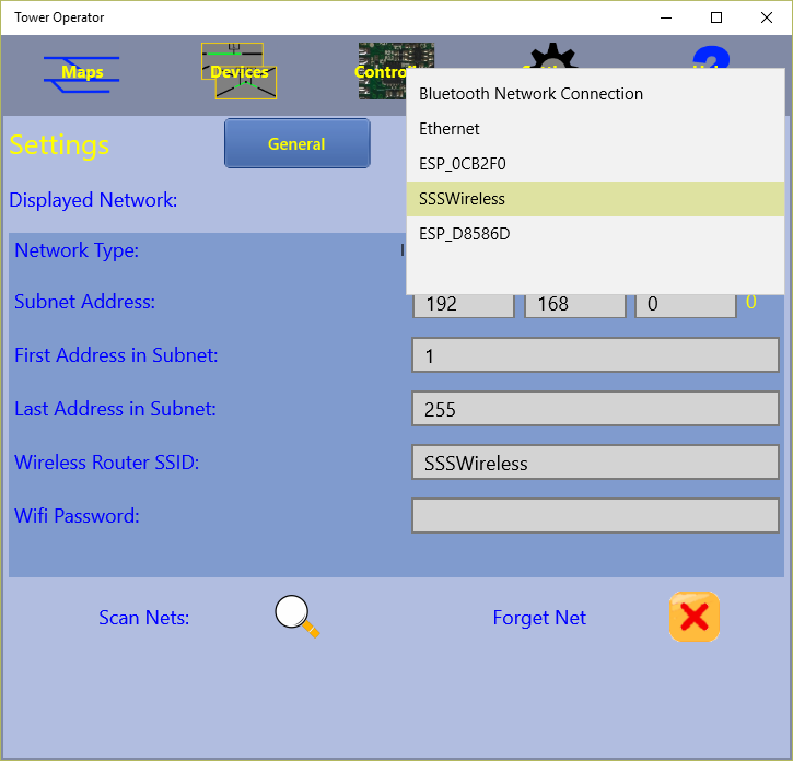
Figure 3 Typical Networks List
In the example, the following networks have been found:
- Bluetooth Network Connection - not relevant.
- Ethernet - the wired LAN to which this computer is connected.
- ESP_0CB2F0 - a new WifiTrax controller.
- SSSWireless - the infrastructure Wi-Fi network provided by the network router.
- ESP_D8586D - a new WifiTrax-installed locomotive.
Note that the last six digits of the Wi-Fi Layout Controller Networks are the last six digits of the AP MAC address printed on the label of the bag in which your WifiTrax controller module was shipped.
For each Infrastructure Network, a range of IP addresses can be reserved for WifiTrax controllers to use when acting as stations.
There are six pieces of information displayed when a network is selected.
- Network Type - Controller AP, Infrastructure AP or Wired LAN.
- Subnet Address - this must match the subnet of the router DHCP controlling the network (DHCP is a protocol the router uses to assign IP Addresses to all devices on its network).
- First Address in Subnet - the first IP Address dedicated to WifiTrax controllers.
- Last Address in Subnet - the last IP Address dedicated to WifiTrax controllers.
- Wireless Router SSID - the SSID of the wireless access point of the network.
- Wifi Password - the password required for a station to connect to the network access point.
For a Controller AP, the subnet address will always be 192.168.4.0. For an infrastructure AP or Wired LAN, you must check the subnet address against your router and change it if needed, but it will default to the most common: 192.168.0.0.
For a Controller AP, the start and end address will always be 1, since there is only one controller on that (its own) network. For an infrastructure AP or Wired LAN, the range defaults to 1 - 255 but you should limit it to a smaller range and assign reserved IP addresses to your WifiTrax controllers. The range entered here is the range that will be scanned for Wi-Fi Layout controllers. The IP addresses actually assigned wil be under control of your Network Router DHCP.
For a Controller Network, the Wireless Router SSID is defined by the WifiTrax module and is of the form ESP_XXYYZZ, where XX, YY and ZZ are the last three pairs of digits of the Access Point MAC (AP MAC) printed on the bag label of the WifiTrax module, e.g ESP_090E31 for a MAC address ending in -09-0E-31. For an infrastructure network, the SSID is that of your Wi-Fi access point. For a wired LAN network, it is not relevant. A MAC (Media Access Control) Address is a unique address given to any device that accesses a network - not the same as the IP address - and we can always use it to uniquely identify each WifiTrax module.
The Wifi password is only needed, for an Infrastructure Network, if you want your controllers to act as stations on that infrastructure network. The password will be given to each controller so that it can connect to your protected infrastructure access point.
Network Re-Scan

You can re-scan your networks at any time by clicking or tapping the Scan Nets button existing networks known to the system will not be lost and any new ones will be added.

You can also remove a net from the system by selecting it in the Displayed Network drop-down and clicking the Forget Net button.
General Settings
These are accessed from the General page of the Settings tab. Tap the settings tab first and then the General button.
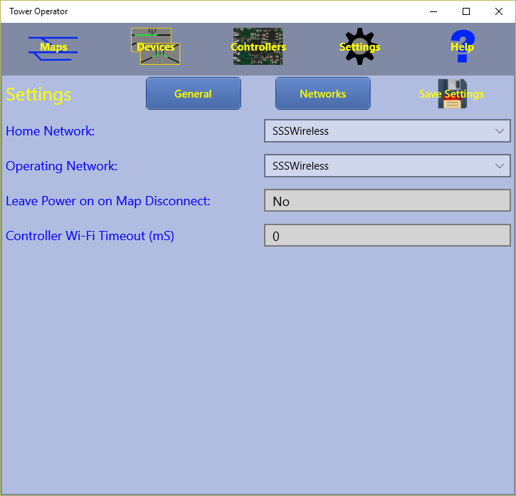
Figure 4 General Settings Page
Home Network
The first setting on the General Settings page is the Home Network. This is the Infrastructure Network that will be given to Wi-Fi Layout Controllers for them to connect to as stations. All the controllers that have been given this information will automatically connect to the home network and can then be controlled when that network is selected as the Operating Network - see below.
You must set up the IP Address range, SSID and Password for the network you choose as home using the Networks page as described earlier. Also you should configure your network router to reserve IP Addresses within that range for each controller MAC Address. You only need to do this if you limit the IP Address range. You can leave it as 0 - 254, but scanning for controllers will take a long time.
To give the Home Network information to each controller, you use the Controllers tab, see the Controller Tunings section in these pages.
Operating Network
The next setting on the General Settings page is the Operating Network. This is the Network that will be scanned when you use the Controllers page and on which you can select controller channels to map to logical device control points.
The operating network can be either an Infrastructure Network, a Wired LAN Network or a Controller Network. For example, if you have a new switch machine controller that has not yet joined the home network as a station, you can configure it on its own Controller Network by selecting that as the Operating Network. When you do this, you must connect your computer, tablet or phone to that network's access point using the Settings, Wi-Fi pages on the computer, tablet or phone that you are using.
In another example, you may want to use a Windows 10 desktop that has no Wi-Fi adaptor. Here you would choose your Wired LAN network as your operating network.
Once you have all your controllers acting as stations on your Home Network, for a Wi-Fi accessible computer, tablet or phone, you will want to choose the Home Network as the Operating Network. Then you will be able to configure all the controllers on the network, assign their capabilities to logical devices and use maps to control your entire layout.
Leave Power On on Map Disconnect
This setting must be Yes or No. If Yes, it will allow you to diconnect from your layout without turning off power controlled by your Power Block control modules such as WFP-40. You will need this if you have more than on computer or tablet controlling the layout and want to leave the power on for the other users..
Controller Wi-Fi Timeout
The time-out used by the device before determining that a controller is not responding may be changed here.
Wi-Fi Layout Controller Management
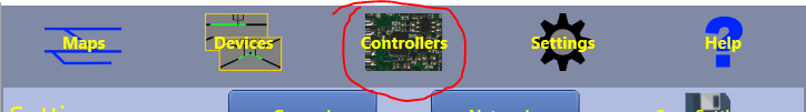
Figure 5. Controllers Tab
Scanning for Controllers
On the Controllers tab, you can manage the controllers that are present on your Operating Network. When you display this tab it will show the controllers on the operating network that are already known to the Tower Operator app. Of course when you first use the App, there will be none.
This tab shows the name of the selected Operating Network. Scans for new controllers and communication with known controllers will occur on this network.
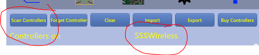
Figure 6. Scan Controllers Button
You can cick the Scan button to scan the network for the Wi-Fi Layout Controllers that are present.
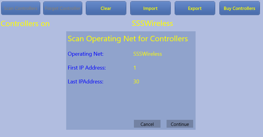
Figure 7. Controllers Scan IP Address Range
The scan will take place over the range of IP addresses that you have defined for the network that is selected as the operating net. In the example shown, the range is from 0 to 30 in the subnet. In this case the scan will not take a very long time. You can reduce this time by limiting the IP range of the network on the Settings tab, Networks page even more, but you must make sure that the router will assign IP addresses to the locomotives within this range. You can do this by assigning reserved addresses to the locomotive controller MAC addresses in your router.
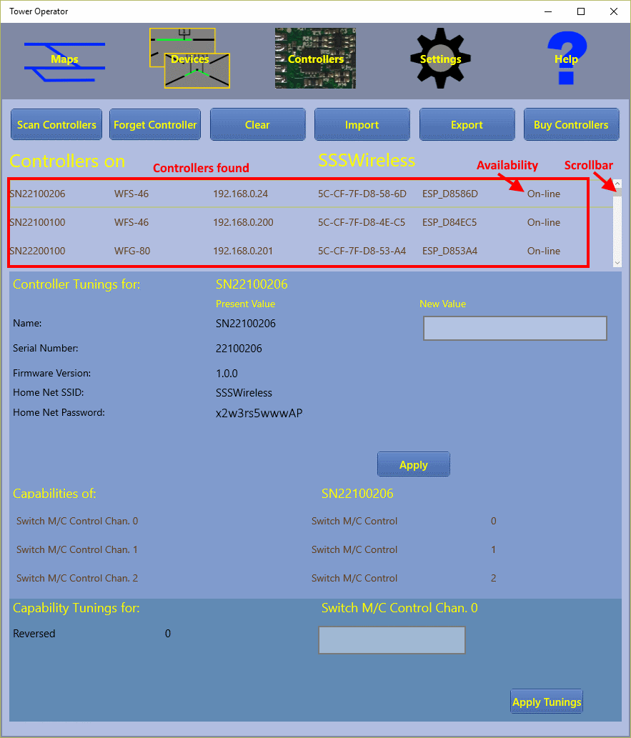
Figure 8. Controllers Found
Once the scan is complete, you will see a list of the controllers that have been discovered on the operating network. You can repeat the scan at any time. New controllers will be added and existing ones updated but existing controllers that are no longer visible (because they are powered down perhaps) will not be removed. If the controllers have not been assigned reserved IP addresses in your router, the IP addresses assigned to a controller may change. The scan operation will update the IP addresses stored by Tower Operator, provided those controllers are powered and accessible when the scan is done.
As well as the network, this page also shows the availability of each controller on it. Any that have been discovered in the latest scan will be available, but older ones may be unavailable if they are now powered down or removed from the track. Available controllers are marked "On-Line".
In the list of controllers, each line includes the name of the controller, which is set at the factory to SN followed by its serial number, its product type, its assigned IP Address and its Wi-Fi SSID.
Under the list of controllers is an information display for the selected controller that also provides the ability to configure "tunings" (or settings) for the controller. In the case of the selected controller, SN22100206, its name, serial number, firmware version and Home Net settings are displayed. In fact, only the Name can be changed by the user for this product type - the WFS-46 Universal Switch Machine Controller. The owner of the model railway, might like to give the controller a meaningful name. Perhaps it controls all the switches in, say, Hughes Yard. Then it might be given the name "Hughes Yard Switches". To change the name, type in a new value and click Apply.
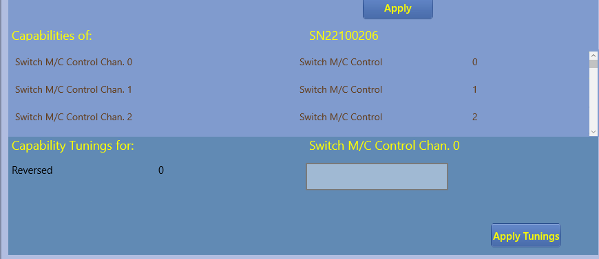
Figure 9. Controller Capabilities
Further down on the screen is a list of the capabilities of the selected controller. Each Wi-Fi Layout Module provides certain capabilities and usually a capability is associated with a channel. For example, the WFS-46 has four switch machine control capabilities, each one with it's own channel number - 0 to 3. These appear in the screen shot above, although only three are visible and you would use the scroll bar to see the other. Each channel can be used to control one tie bar of a switch. Another example, the WFG-80 has eight Light Control Capabilities and two dimmer capabilities. Each Lighting control capabaility has a channel number - 0 to 7 and the dimmers have channel numbers 0 to 1.
Some capabilities have tunings that apply to just that capability. In the screen shot, since Switch Machine Control Chan. 0 is selected in the list, its tunings are shown below. In this case there is only one called "Reversed". This can be set to 0 or 1. When set to 1, it reverses the direction of the switch so that Thrown becomes Straight and Straight becomes Thrown. This is very useful if you have wired the coils of a twin-coil switch machine with the coils swapped. Changing this value to 1 will correct matters so that it will show correctly on your map. To change the value, type 0 or 1 in the text box and click Apply Tunings.
Deleting Controllers
You can remove a controller from the local database by selecting it in the list and clicking or tapping the Forget Controller button. You can always add the controller again by powering it up and repeating the scan.
You can also remove all the controllers from the local database by clicking the Clear button. Then you can begin again. Note that controller and capability tunings are stored in the controller modules themselves not in the local database. Therefore they are not lost when controllers are removed from the local database.
Exporting Controllers
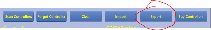
Figure 10. Export Button
You can export all the controller that have been recorded in the local database by clicking the Export button. This will create a file that you can name. In Windows, this is placed in the Roaming State folder which means that it will be synchronized to the corresponding folder on all the devices in which you have Tower Operator installed. Once you have scanned all your controllers, you can then export them and import them to other devices that may not even be connected to the layout.
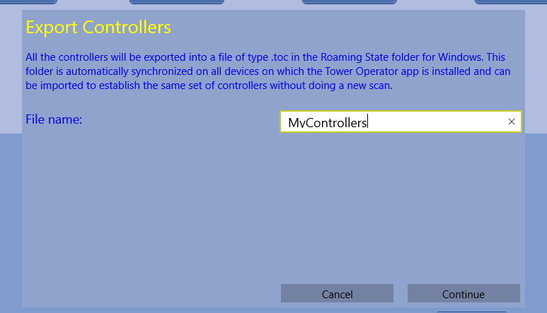
Figure 11. Export Dialog
Importing Controllers
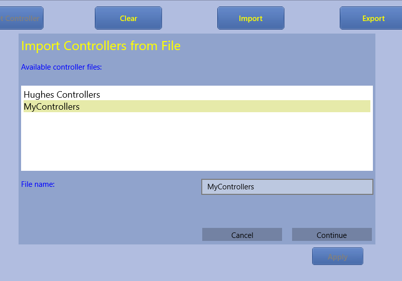
Figure 12. Import Dialog
To import all the controllers from a file, click the Import button. The above dialog will display. You must select one of the files shown in the list. Click Continue and all the controllers will be imported.
Logical Devices
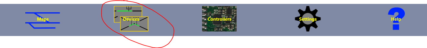
Figure 13. Logical Devices Tab
Select the Devices tab to create and configure logical devices such as switches, signals, lights and power districts.
What are logical devices?
Logical devices are devices that you can control that represent active physical features on your layout. Examples are switches (points or turnouts if you prefer), signals, lights, turntables, power districts, occupancy detectors, house lighting. What else can you think of? Each logical device has a symbol which can be placed on one or more maps of parts of your layout and used to control a corresponding physical device.
Let's consider a right hand switch. You can create a right hand switch logical device called S1, say, and place it on a map. Somwhere on your layout will be a real switch, fixed to the baseboard that you want your logical switch S1 to represent. How do you associate one with the other? Part of it involves modules and wiring. The other part involves a setting in Tower Operator.
Lets consider the physical part first. First you have to buy one of our WFS-46 or WFS-86 Universal Switch Machine Controllers (or some other, yet to be released product). Then you have to set its little DIP switches correctly for the type of physical switch you are using. E.g. Tortoise stall motor machines need a different setting to Peco twin-coil. Next you need to install the controller somewhere suitable on your layout, near to the switches it will control. Then you have to wire the screw terminals to the connections of your switch machines.
This is all described clearly in the Quick Start leaflet for each type of module.
Finally, there's the settings in Tower Operator: you have to associate the control points of your logical device S1 with a sitch machine capability - i.e. one of the WFS-46's channels. So that's the theory and in the following we'll go through how you do this in Tower Operator.
Creating a Simple Logical Device
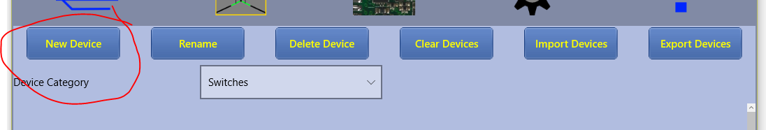
Figure 14. New Logical Device Button
To create a new logical device, click or tap the New Device button.
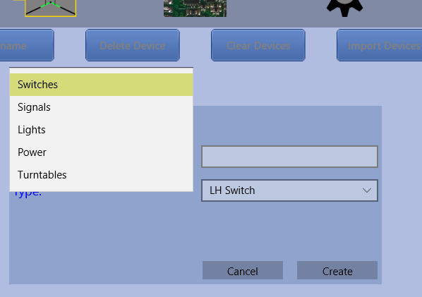
Figure 15. Select the Logical Device Category
Select the required category, then select the type.
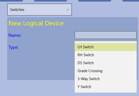
Figure 16. Select the Logical Device Type
There are quite a few logical device types defined in Tower Operator, including many kinds of switches and crossings including 3-Way Switch and Double Slip Switch. There are also various types of signals, lights, power districts and turntables. More logical device types will be added in future upgrades of Tower Operator.
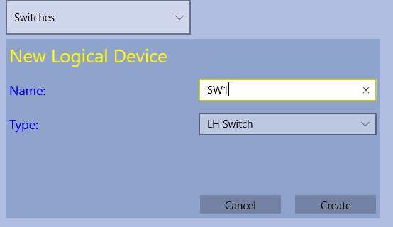
Figure 17. Type the Logical Device Name
Type a name for the logical device, then click Create.
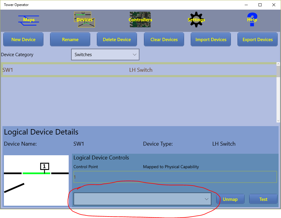
Figure 18. New Logical Device
Assigning Controller Capabilities to a Simple Logical Device
The Devices screen shows the new device. At the bottom of the screen is the detail pane for the selected device. It contains basic information at the top. To the bottom left is a schematic image of the device showing any control points that it has which are numbered. In this case there is one control point, the tie bar labeled "1". This corresponds to a row in the Logical Device Controls list to the right of the image. Initially, there is nothing in the "Mapped to Physical Capability" column. This means that there is no physical controller capability assigned to this control point.
To correct this, click on the Available Capabilities drop-down as circled in red above and select a capability to implement the tie bar control point.
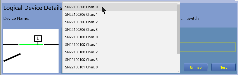
Figure 19. Select the Controller Capability
The figure above shows that we have quite a few to choose from here. We'll choose the first one.
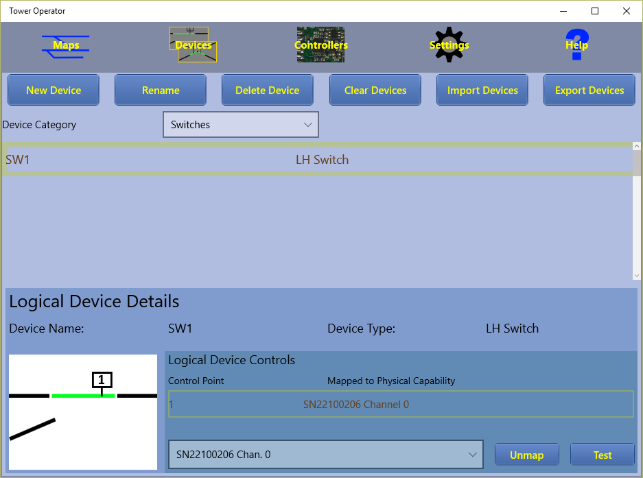
Figure 20. Completed Device
The screen now shows the fully configured left hand switch. We can test this by clicking the Test button to the right. This should make the switch's tie bar operate.
A More Complicated Logical Device
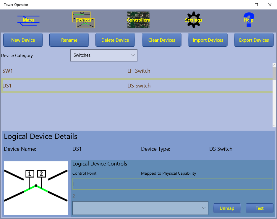
Figure 21. Double Slip Switch Device
The screen above shows a more complicated switch, a double slip switch. The schematic image on the left shows that there are two control points - two tie bars - that need to be assigned to controller capabilities and the Logical Device Controls list now has two entries both of which need to be assigned.
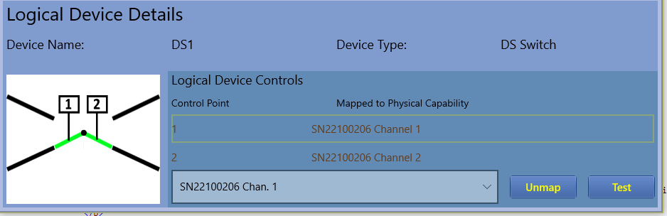
Figure 22. Double Slip Switch Device Fully Assigned
These can be assigned to two more channels of the same controller as shown above. Using the Test button should cycle through all four states of the double slip switch. To check it properly, you need to place it on a map since the images here do not change. In fact you may need to change some wiring or reverse the capabilies on the Controllers screen to get the physical position to match the symbol shown on the map.
Operating Switches Together
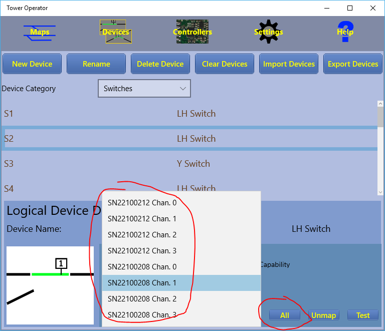
Figure 23. Displaying All Capabilities instead of Spare Capabilities (Version 2.0)
Sometimes there are cases in your track design where you always operate two or more switches together. One obvious case is a crossover between two parallel tracks. There's no sense in throwing one switch without the other! WifiTrax Switch Machine Controllers are all powerful enough to operate two switch machines at the same time. In many cases, they will operate more than two - certainly stall motor machines will be no trouble. Version 2.0 of Tower Operator provides a means of assigning a controller channel to a control point of more than one logical device.
Normally, the Available Capabilities drop-down list only shows those controller channels that are NOT already assigned - "Spare" capabilities. However if you click the button just to the right that normally shows "Spare", it will toggle to "All" so that all the capabilities (controller channels suitable for switch machines) will be available for selection. Then, once you have chosen an unused capability for the first switch machine of your crossover, you can change to "All" and select the same capability for the second switch machine.
Then, when you have made your crossover on your map, you can be sure that when you click or tap one switch, the other will change as well both on your map and on your layout.
Power Districts
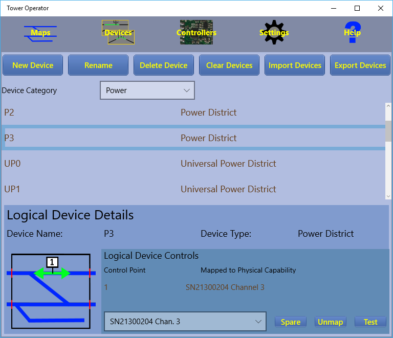
Figure 19. Power Districts on the Logical Devices List (Version 2.0)
In Tower Operator Version 2.0, the Power Category of logical devices includes two types of Power District or Power Block - we use the terms interchangeably, "Power District" and "Universal Power District". The first type controls power to a double-isolated section of track. The logical device will appear on your maps as a red box that can be adjusted to enclose a part of your track plan. You should adjust the boundaries on your map to correspond approximately to the the gaps in your track. The positioning of the boundaries is only to remind you and has no other function. When included in your map, and connected with power on, the Power District will indicate the presence of a locomotive and the current being drawn. It will allow you to reverse its electrical polarity (direction) and turn it off. It will also shut down if an overload is detected and automatically reverse as a locomotive goes over gaps between districts whose directions are opposed. This allows for return loops, wyes and turntables.
The second type, Universal Power District is central to WifiTrax Wi-Fi DC technology and can be mapped to a channel on a module such as the WUFP-47. It provides the same features as the ordinary Power District, but also provides the ability to drive a DC locomotive within it. Once you have a Universal Power District on your map, you can click on it's control buttons to select 4 modes: WifiTrax, Chan A DC, Chan B DC or External DCC.
In the WifiTrax (WFX) mode, DC is applied to the track in the power district. This allows you to drive locomotives equiped with WifiTrax decoders using our Loco Operator app. You have the full benefit of auto-reverse for return loops.
In the Chan A DC (CHA) mode, pulse width modulated (PWM) power is applied to the track and the back e.m.f. of the motor is monitored by the electronic module. A driving capability appears on your Wi-Fi network just like a WifiTrax equiped locomotive. The difference is that it drives whatever DC loco is present on the track. You can use the Loco Operator app to drive the locomotive by selecting Chan A of the hardware module. Note that in Chan A or B DC mode, the Auto-Reverse feature may not always work. This is because the PWM voltage to DC locomotives varies and may not be sufficient to trigger the auto-reverse capability reliably. You may therefore have to reverse blocks manually as a DC locomotive traverses a return loop.
In the Chan B DC (CHB) mode is the same as Chan A DC except that it connects the B channel of the module to the track, so you drive by selecting the B channel in Loco Operator. If you use a WUFP-47, there are four power block channels, so you can be driving two locomotives together by assigning some blocks to Chan A DC and some to Chan B DC. This feature will be developed further in later versions of Tower Operator and Loco Operator so that you can use more than one module such as WUFP-47.
In the External DCC (EXT) mode, you can connect your DCC Command Controller or Booster to the External inputs on your WUFP-47 or similar module. You can then drive locomotives equiped with DCC decoders on the track within the district. You have the full benefit of auto-reverse for return loops.
You can create Power Districts using the New Device dialog, selecting the Power category and the type of Power District you require.
Creating and Editing Maps
Figure 25. Maps Tab
Select the Maps tab to create, edit and use maps of all or sections of your layout. You can then connect the map tou your layout and use it as a Schematic Control Panel.
What is a Map?
A Map is a diagram of part or all of your layout in a schematic form. This means that it is not intended to accurately represent the actual shape of your layout features such as track, terrain etc. Rather, it is intended to prepresent connectivity of tracks and relationship to other features in more of a topological manner. The best example is perhaps a subway map. It shows the relationships between stations, Compass directions, North South East and West are correct, but there is no real scale or accurate depition of exact spacial relationships. The best example is a Schematic Control Panel of the type that is usually seen in modern signal towers and on many model railroads.
Creating a New Map
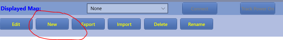
Figure 26. New Map Button
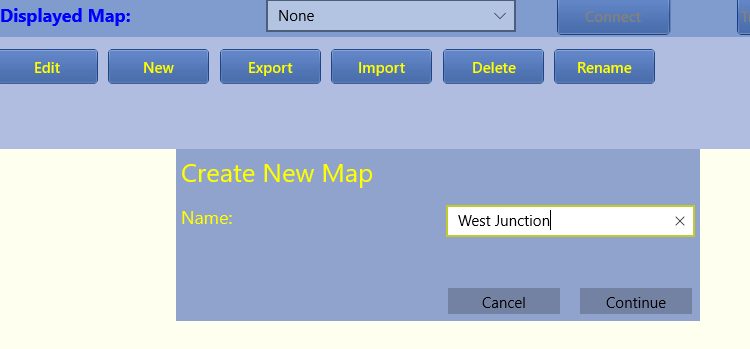
Figure 27. New Map Dialog
Click the New button, type a name and click Continue.
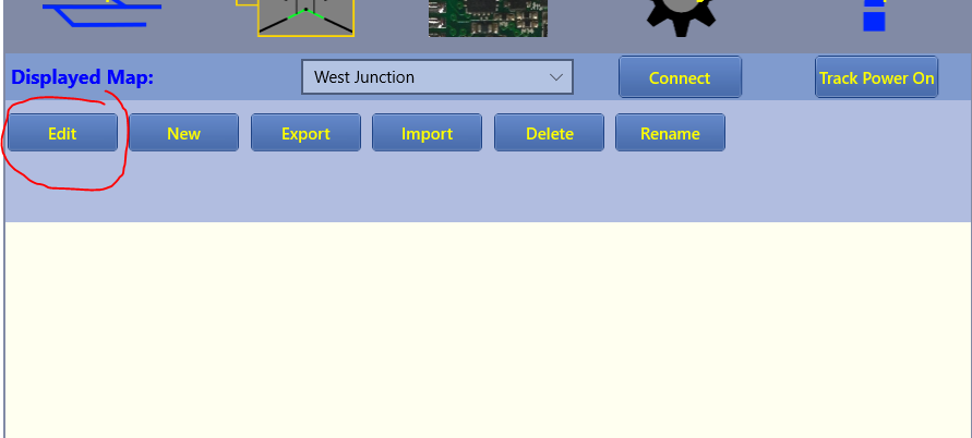
Figure 28. Maps Screen Showing the Newly Created Map
Figure 28 shows the Map Screen with the new map showing. It is blank so the next thing is to click the Edit button to enter Edit mode, so that a Map can be designed.
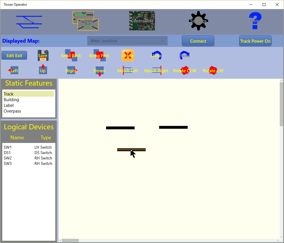
Figure 29. Maps Screen in Edit Mode - adding tracks
Figure 29 shows the Map Screen with the new map in Edit Mode. In this mode two toolbox areas appear at the left. At the top left is the Static Feature Toolbox. This lists Stati Features that may be placed on the map in any quantity. Static features are features that you would like to show in your schematic map that do not represent a physical feature that can be made to do anything on the layout.
Indeed some static features like Label do not represent physical features on the layout at all, whereas track certainly does something but it remains fixed and does not change. Buildings also remain static. They may contain lights or other parts that move, but these appear separately on the schematic map.
To place a static feature on the map, simply click on the feature in the Static Featore Toolbox, then click on the map. If you know you want to place more than one instance of the feature, such as several buildings or several sections of track, hold down the control key while clicking on the feature name. Then each time you click on the map, a new instance of the feature will appear. To end this sequence, hit the escape key. Figure 29 shows the act of placing several lengths of track on the map.
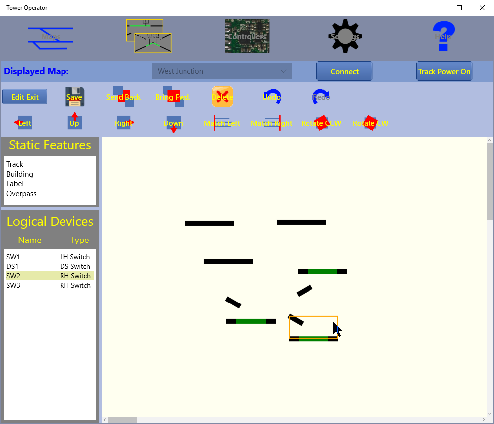
Figure 30. Maps Screen in Edit Mode - adding switches
Figure 30 shows the Map Screen with the new map in Edit Mode and the user is now adding several switches to the map. Each switch must have been created previously in the Devices screen as described before. It is not necessary to assign controller capabilities to their tie bars at this stage, but of course you will not operate a physical switch until you have done that.
All logical devices such as switches appear in the Active Feature, or Logical Devices Toolbox at the lower left of the screen. Logical devices represent physical devices and therefore they can only be used once on any particular map. However you can place the same device on more than one map. Obviously, if the maps have different topology this makes no sense, but if two maps represent different views of the same layout - for example on is a magnified view of a station, whereas the other represents the entire layout - then it would make sense. It is up to you to use this feature effectively.
To place an active feature, that is an instance of a logical device on the map, click orn the logical device name in the Active Feature Toolbox, then click on the map. An image of the device will appear. If you clicked on a device that was already on the map, the device image will be outlined to indicate its position and you will not be able to add another instance of it.
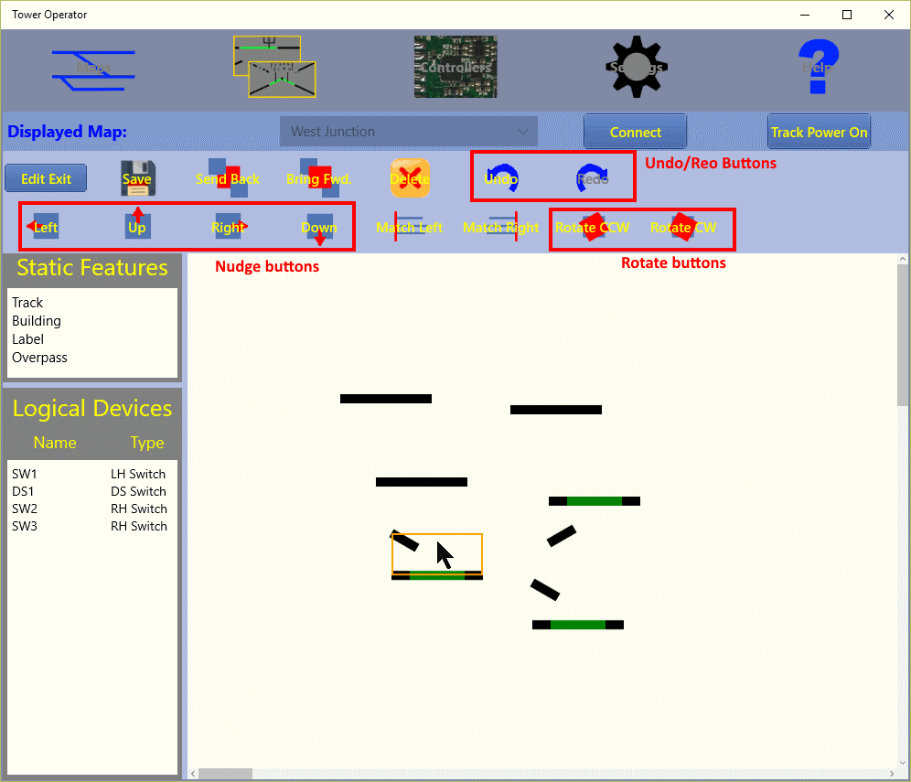
Figure 31. Maps Screen in Edit Mode - adding switches
Figure 31 shows the user moving active and static features into position. You can select either a static or active feature by clicking on it. Once selected it is outlined in yellow. It can be moved by dragging it with the cursor or by using the left, right, up or downn arrows of the keyboard. To move only a small amount hold down the shift key and use the arrow keys. Instead of the keyboard, you can use the Nudge buttons that are outlined in Figure 31.
You can also select multiple devices by holding down the control key and clicking the devices in turn. You can also select multiple devices by dragging the mouse cursor from the top left towards the bottom right to mark a fame around a set of features. To deselct the devices just click anywhere on the map.
You can rotate any feature by selecting it and clicking the rotate buttons. The Rotate CCW button rotates 15 degrees counter-clockwise and Rotate CW rotates the same amount clockwise.
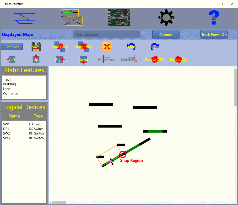
Figure 32. Maps Screen in Edit Mode - adding switches
Figure 32 shows how features can be joined together. If you drag an active feature that has track connections like a switch (or actually a turntable), when the connection points come close to either a connection point on another switch or the end of a track, they will snap together, ensuring that the system will regard them as joined for the purpose of routing. Figure 32 shows this snap region in red.
You can move the ends of tracks by moving the cursor over the ends at which time a red circle will appear to show that the end can be moved to any position. It is a good idea perhaps to maintain only 30 or 15 degree angles though, so that the schematic map looks tidy.
You can constrain movement of a feature or the end of a track to be vertical or horizontal ONLY by holding down the shift key and dragging in the vertical or horizontal direction to start. The movement will be constrained to be only in the vertical or horizontal direction according to your starting movement. Many drawing programs follow this same approach.
To delete a track or active feature, select it and use the delete key or click the delete button.
If you make a mistake, you can click the Undo button, outlined in Figure 31. You can repeat this a number of times although there is a limit. You can then click the redo button to redo the undo. You can achieve the same result with control Z and control Y on the keyboard.
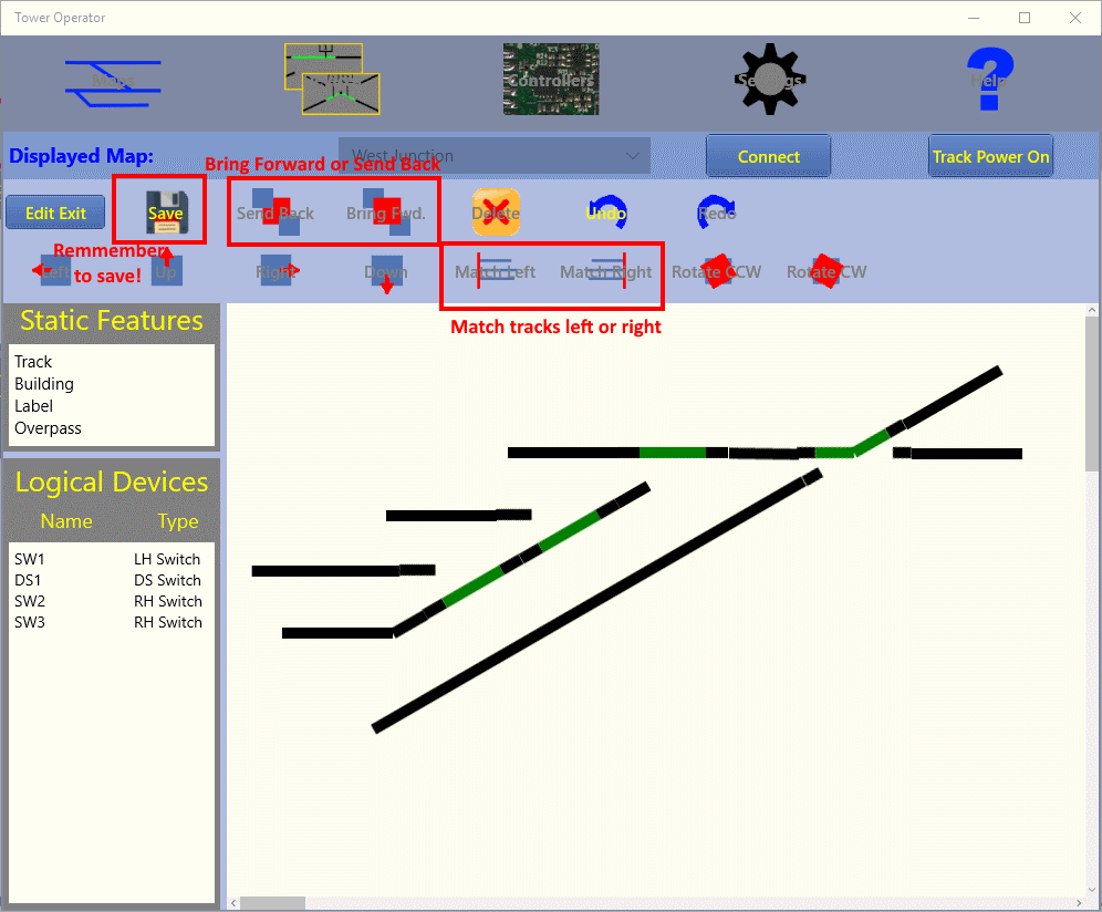
Figure 33. Maps Screen in Edit Mode - nearly complete
Figure 33 shows a map that is nearly complete. We would like all the tracks in the freight yard to line up at the left. This can be achieved using the Match Left or Right buttons outlined in Figure 33. Select all the required tracks by holding down the control key and clicking each, then click the Match Left button.
We can add an overpass or bridge by clicking Overpass and the clicking on the map. Here we use another feature, the Send Back and Brig Forward buttons. If we find the bridge above the track, we can select it and click the Send Back button until it is under the track.
Be sure to click the save button frequently to save your edits, but you can't undo after a save.
We can add some buildings and labels to the map. The click Save and Edit Exit.
Finally we can go back to the Devices screen and create some signals and lights, edit the map again and add them..
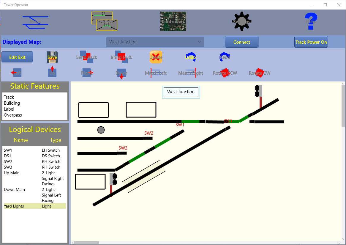
Figure 34. Maps Screen in Edit Mode - added the signals and yard lights.
Figure 34 shows the completed map with signals and yard lights added. Click Save and Edit Exit. To enter Run Mode. We'll discuss that in the next section.
Controlling your Layout
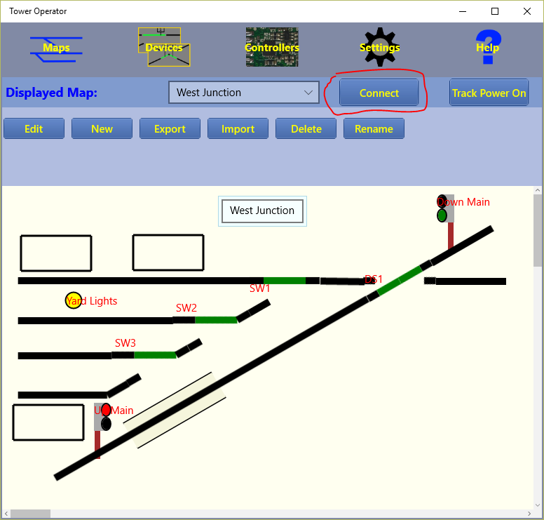
Figure 35. Maps Screen in Run Mode
Figure 35 shows a map ready to be used as a schematic control panel.
To connect to the layout, click the Connect button.
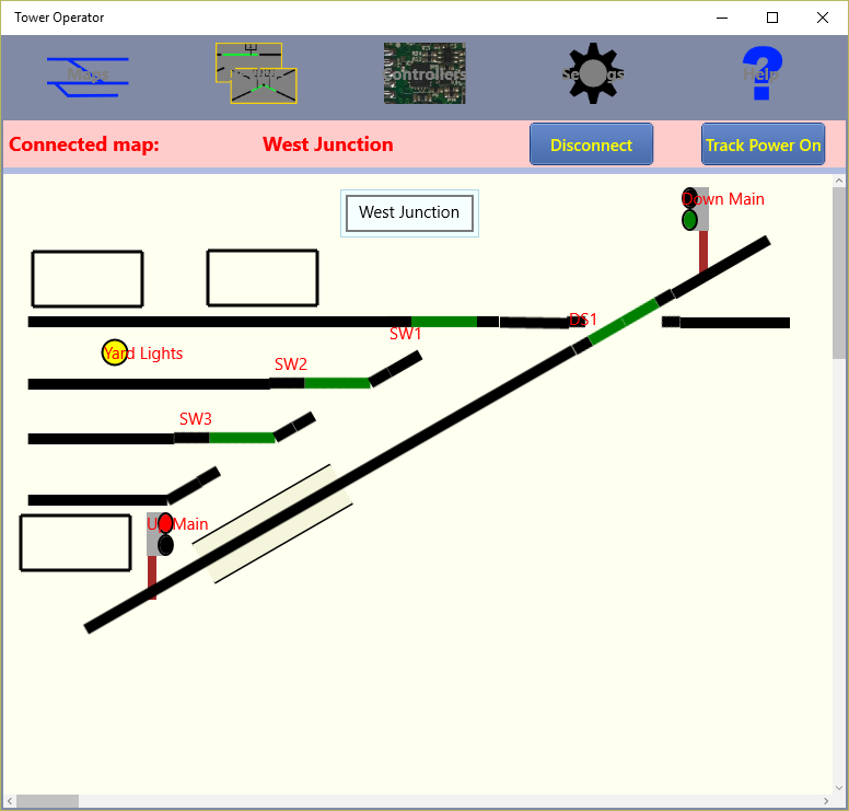
Figure 36. Maps Screen in Run Mode, Connected
Figure 36 shows a map connected to the layout. Clicking or tapping on any active feature causes it to switch to its next state. For instance Left and Right Hand Switches go from straight to thrown and back. Signals go from red to green and back to red. 3-Light signals include amber in the sequence. Double Slip Switches and 3-Way Points go through all their possible positions in sequence.
Different features behave in different ways, turntables will go through all their positions. Power blocks change polarity on tapping.
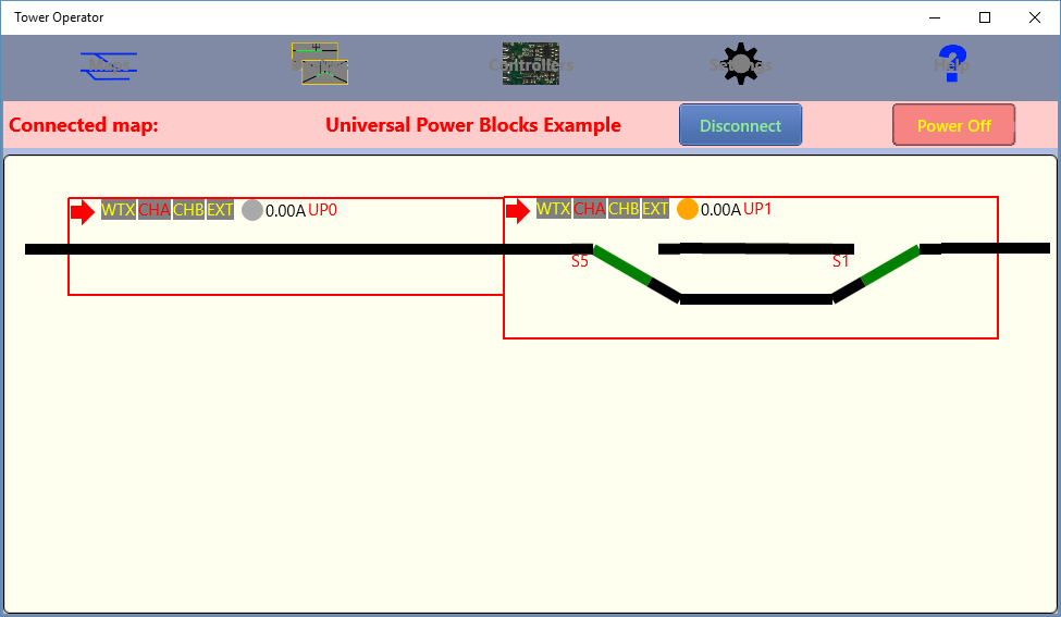
Figure 37. Maps Screen in Run Mode with Universal Power Districts, Connected
Figure 37 shows a map containing some universal power districts connected to a layout. Clicking or tapping on one of the Mode buttons: WTX, CHA, CHB and EXT causes that power mode to be selected for the section of track under control of that district. Clicking or tapping on the red arrow icon causes the direction to sequence between left, right and off.
The Current indicator show the current being drawn by the locomotives in that block. The Occupation indicator shows yellow when the block is occupied by a locomotive, whether running or not. The text in red is simply the name of the logical unit for the Universal Power District.